


Hardware components | ||||||
 |
| × | 3 | |||
 |
| × | 1 | |||
 |
| × | 1 | |||
| × | 1 | ||||
 |
| × | 1 | |||
| × | 1 | ||||
| × | 1 | ||||
| × | 1 | ||||
| × | 1 | ||||
| × | 1 | ||||
| × | 1 | ||||
Hand tools and fabrication machines | ||||||
 |
| |||||
 |
| |||||
I've recently posted a tutorial about this project on YouTube explaining everything you can read on this article. You can watch it right below.
IntroductionIn this tutorial, I'll show you how to build an automatic street light model at home using simple materials like cardboard and a very small electronic circuit.
And here's the best part:
- We won't use Arduino, code, or a ready-made control board.
Instead, we'll create our own PCB using just two materials and let the circuit itself decide when the lights should turn on and off.
This project is part of lesson 13 of the Arduino for Beginners series. Today's goal is to go beyond code and understand how real electronics work at the hardware level.
By the end of this project, you'll:
- Understand how a circuit can react to light without programming
- Learn how a transistor makes decisions using voltage
- Create a real PCB at home
- Build a physical model you can test, display, or use in a science fair
Let's start by looking at what we're building.
Additionally, you can find the supplemental materials (schematic, list of components, etc) on this GitHub repository.
SuppliesFor this project, you'll need:
- 3 × white LEDs
- 1 × BC547 transistor
- 1 × 100kΩ resistor
- 1 × photoresistor
- 1 × 9V battery connector
- Cardboard
- Paper
- Glue
- Copper clad laminate
- Ferric chloride
- Permanent marker (pen)
Earlier in the series, turning a light on at night meant writing an if statement. The Arduino read a sensor value, compared it to a threshold, and executed a decision in software.
In this build, we push that logic into the circuit itself.
When light hits the sensor, the circuit stays inactive. As the environment darkens, voltages shift until the circuit crosses a physical threshold. At that moment, the lights turn on instantly. Nothing executes, nothing loops, and nothing waits. The circuit simply responds.
I need you to understand that this shift really matters. Once you stop relying on code "to think" for you, electronics becomes far more intuitive. You begin to see circuits not as static diagrams, but as dynamic systems that continuously react to their surroundings.
What the Model Actually DoesThe finished project looks like a small street scene with several lamps mounted on a cardboard structure. A light sensor mounted on the side constantly monitors ambient light.
During the day, the lamps remain off. As soon as the light level drops, the lamps turn on automatically. You don't need to press a button or flip a switch. The circuit reacts the moment conditions change.
This immediate feedback makes the project especially effective for learning. Cover the sensor with your hand, and the system responds instantly. Remove your hand, and the lights turn off again. The behavior feels obvious, almost natural - and that's exactly the point.
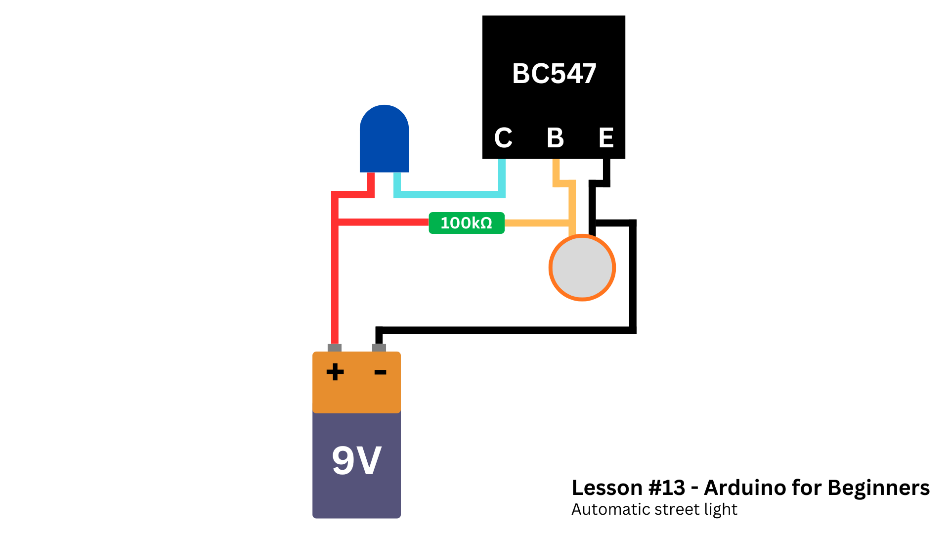
How the Circuit Makes DecisionsAt the center of the circuit sits an NPN transistor. Instead of treating it as a mysterious component, we use it for what it really is: an electrically controlled switch.
The transistor allows current to flow only when the voltage at its base rises high enough. Below that threshold, it blocks current completely. Above it, the circuit activates and powers the LEDs.
The circuit generates that base voltage using a light-dependent resistor paired with a fixed resistor. Together, they form a voltage divider whose output continuously tracks ambient light levels. Bright light forces the voltage down but darkness pushes it up.
As the environment darkens, the voltage at the transistor’s base rises smoothly. Once it crosses the transistor's turn-on threshold, the transistor switches on and current flows through the LEDs.
No binary commands exist here. No explicit "on" or "off" instruction appears anywhere. Voltage simply changes, the transistor responds, and the circuit behaves accordingly. This analog behavior sits at the core of real electronics, and understanding it unlocks far more complex designs.
SponsorBefore diving into the hands-on part, I would like to thank today's sponsor: DFRobot.
If you don't know they yet, DFRobot is a global hardware provider focused on robotics and electronics education.
They've spent more than 15 years designing components that balance quality, affordability, and accessibility - especially for beginners.
Throughout this series, I've been using parts from the MindPlus Arduino Coding Kit, which includes everything needed to start building real projects and understanding how electronics works at a deeper level.
If you want to follow along with the same hardware used in this series, this kit makes that process much easier. Even beyond these lessons, the components remain useful for countless future builds.
A big thank you to DFRobot for supporting this series and helping make hands-on STEM education more accessible to everyone.
Turning the Circuit Into a Real PCBAfter validating the circuit on a breadboard, we'll turn it into a real printed circuit board. Instead of outsourcing fabrication, we'll make the PCB at home using copper-clad board and ferric chloride.
I started by cleaning the copper layer. Use a dry cloth or fine steel wool to remove dirt and oxidation.
I drew the traces directly onto the copper using a permanent marker. The marker protects those paths while the ferric chloride removes the exposed copper around them.
I placed the board into a plastic container filled with diluted ferric chloride.
If using ferric chloride powder:
- Mix 1 part ferric chloride
- With 2 parts water (by mass)
For example:
- One ounce of ferric chloride (28 g)
- And two ounces of water (56 g)
After some minutes, the exposed copper will dissolve.
After etching, I drilled the holes and soldered the components according to the schematic we saw earlier.
This process isn't perfect, and it doesn't need to be. I made a wiring mistake not drawing the traces of the resisotr and fixed it later with soldered yellow wires (as you can see in the next section). What matters is that the final board works reliably and turns the circuit into something solid and reusable.
At that point, the project stops feeling like an experiment and starts feeling like a finished electronic system.
By the way, if you need help with manufacturing your own PCB, I have a tutorial all about that.
Safety Warning (Very Important)Ferric chloride is not a harmless substance.
- It stains surfaces permanently
- It corrodes metal
- It irritates skin
- It can cause serious eye damage
Always:
- Wear gloves and eye protection
- Work in a well-ventilated area
- Use plastic containers only
- Never pour it into a drain
- Dispose of it according to local chemical disposal rules
Safety is not optional.
With the electronics complete, the rest of the project focuses on presentation. Cardboard, paper, and glue are enough to create a simple but effective street-light structure.
You can follow the measurements below to build a cover similar to what I did.
After finishing the enclosure, I soldered the LEDs. The LEDs are wired in parallel so that each lamp receives the same voltage, then mounted inside small paper lamp covers.
Before moving on, I tested the circuit and it worked quite well. Then I put the PCB and battery inside the base and glued it, leaving only the lights and the sensor visible.
This step may seem unimportant, but it plays a crucial role. When electronics is placed inside a physical object, it stops feeling like a lab experiment and starts to look like a real system. That shift in perception is especially valuable for beginners and students.
Why This Project MattersThe most important result of this project is not the street light model itself. It's the understanding that logic does not require code.
Long before microcontrollers existed, engineers built systems that reacted to their environment using nothing more than resistors, transistors, and clever design. This project recreates that idea in a simple, approachable way.
Once you understand how voltage, resistance, and thresholds interact, you gain the ability to design circuits that sense, decide, and act - all on their own.
Final ThoughtsThis automatic street light is a small project, but it represents a big conceptual step. It bridges the gap between programming-based thinking and true electronic design.
In the next lesson, we'll learn about 16x2 LCD screens and how to use them in your Arduino projects.
If you enjoyed reading this article, I'll probably like this one where I teach you how to use LoRa modules with Arduino.
Thanks for reading, and I'll you in the next tutorial.


Comments