


Hardware components | ||||||
 |
| × | 2 | |||
 |
| × | 3 | |||
 |
| × | 2 | |||
 |
| × | 2 | |||
 |
| × | 3 | |||
 |
| × | 2 | |||
| × | 1 | ||||
| × | 1 | ||||
| × | 1 | ||||
Hand tools and fabrication machines | ||||||
 |
| |||||
 |
| |||||
I've recently posted a tutorial about this project on YouTube explaining everything you can read on this article. You can watch it right below.
IntroductionPrinted circuit boards (PCBs) often feel like a "next level" skill in electronics - something reserved for factories, expensive machines, or professionals. But the truth is much simpler.
In this article, I'll show you how to manufacture functional PCBs at home using just two core materials, simple tools, and a small workspace.
If you've never made a PCB before, this guide will give you a complete and practical starting point.
Additionally, you can find the supplemental materials (schematic, list of components, etc) on this GitHub repository.
SuppliesHere are the components and materials we'll use today:
- 2 × BC547 transistors
- 3 × 5mm LEDs (any color)
- 2 × 100 µF electrolytic capacitors
- 2 × 10 kΩ resistors
- 3 × 2 kΩ resistors
- 2 x 9V battery connector
- Copper clad laminate
- Ferric chloride
- Permanent marker (pen)
If you've been building electronic projects for a while, chances are you've used breadboards in almost everything you've made.
Breadboards are excellent for prototyping:
- No soldering required
- Circuits can be modified quickly
- Wiring mistakes are easy to fix
- Perfect for learning and experimentation
For early testing, they are hard to beat.
However, breadboards have serious limitations once a project needs to last longer than a quick test.
- The circuit becomes physically large
- Connections are unreliable
- A small movement can break contact
- Vibration and transportation cause failures
Breadboards are simply not designed for long-term or real-world use. If you want your project to feel solid and professional, you need something more robust.
Perfboards: Better, But Still Not IdealThe next step many people take is using perfboards or universal boards. These allow you to solder components instead of plugging them in, which improves mechanical strength.
But a new problem appears very quickly.
- Wiring becomes messy
- Traces are hard to follow
- Debugging large circuits is difficult
- The final result often looks improvised
It works - but it’s not elegant (as you can see in the photos above).
This is where printed circuit boards become essential.
What a PCB Actually DoesA printed circuit board does two fundamental things:
1. Mechanical stability
Every component is physically secured in place. Nothing moves, and connections remain stable over time.
2. Electrical organization
Copper traces define exact electrical paths, replacing loose wires with predictable and intentional connections.
This is why every modern electronic device relies on PCBs:
- Phones
- Computers
- Industrial controllers
- Medical devices
Even though modern PCBs may look complex, the core idea behind them is surprisingly simple:
Protect the copper you want to keep, and remove the rest.
That’s exactly what we’ll do.
The Two Materials ChallengeTo show how accessible PCB manufacturing really is, this entire process is limited to only two core materials:
- Copper clad laminate
- Ferric chloride
No CNC machines.
No UV exposure boxes.
No expensive equipment.
Everything can be done on a small desk with simple tools.
The goal here is not factory-quality boards, but real, functional PCBs that you can actually use in your projects.
Now let's understand the materials we'll use today.
Copper Clad Laminate
This is a fiberglass or resin board coated with a thin layer of copper on one or both sides. The copper layer will become the electrical traces.
Ferric Chloride
Ferric chloride is a chemical etchant that reacts with copper and dissolves it.
By protecting specific areas of copper, we control where copper remains. Those protected areas become the traces that connect the electronic components.
Safety Warning (Very Important)Ferric chloride is not a harmless substance.
- It stains surfaces permanently
- It corrodes metal
- It irritates skin
- It can cause serious eye damage
Always:
- Wear gloves and eye protection
- Work in a well-ventilated area
- Use plastic containers only
- Never pour it into a drain
- Dispose of it according to local chemical disposal rules
Safety is not optional.
The first project is intentionally simple. The goal is not electrical complexity, but understanding the PCB fabrication process.
For this project, you'll need:
- 1 × 5mm LED
- 1 × 2kΩ resistor
- 1 × 9V battery connector
Step 1: Clean the Copper
Start by cleaning the copper surface using a dry cloth or fine steel wool to remove dirt and oxidation.
A clean surface is critical for proper etching.
Step 2: Draw the Traces
Using a permanent marker, draw the traces directly onto the copper.
The marker ink acts as a resist, preventing ferric chloride from reaching the copper underneath.
This technique works surprisingly well for simple circuits.
Step 3: Etch the Board
Place the board into a plastic container filled with diluted ferric chloride.
If using ferric chloride powder:
- Mix 1 part ferric chloride
- With 2 parts water (by mass)
For example:
- One ounce of ferric chloride (28 g)
- And two ounces of water (56 g)
Some tips:
- Gently move the container every few minutes
- Keep the copper facing downward so etched copper doesn’t settle on the board
After some minutes, the exposed copper will dissolve.
Step 4: Clean and Finish
- Rinse the board with water
- Remove the marker ink using alcohol
- Drill the holes
- Solder the components
Once powered, the LED lights up exactly as expected - confirming that the PCB process worked.
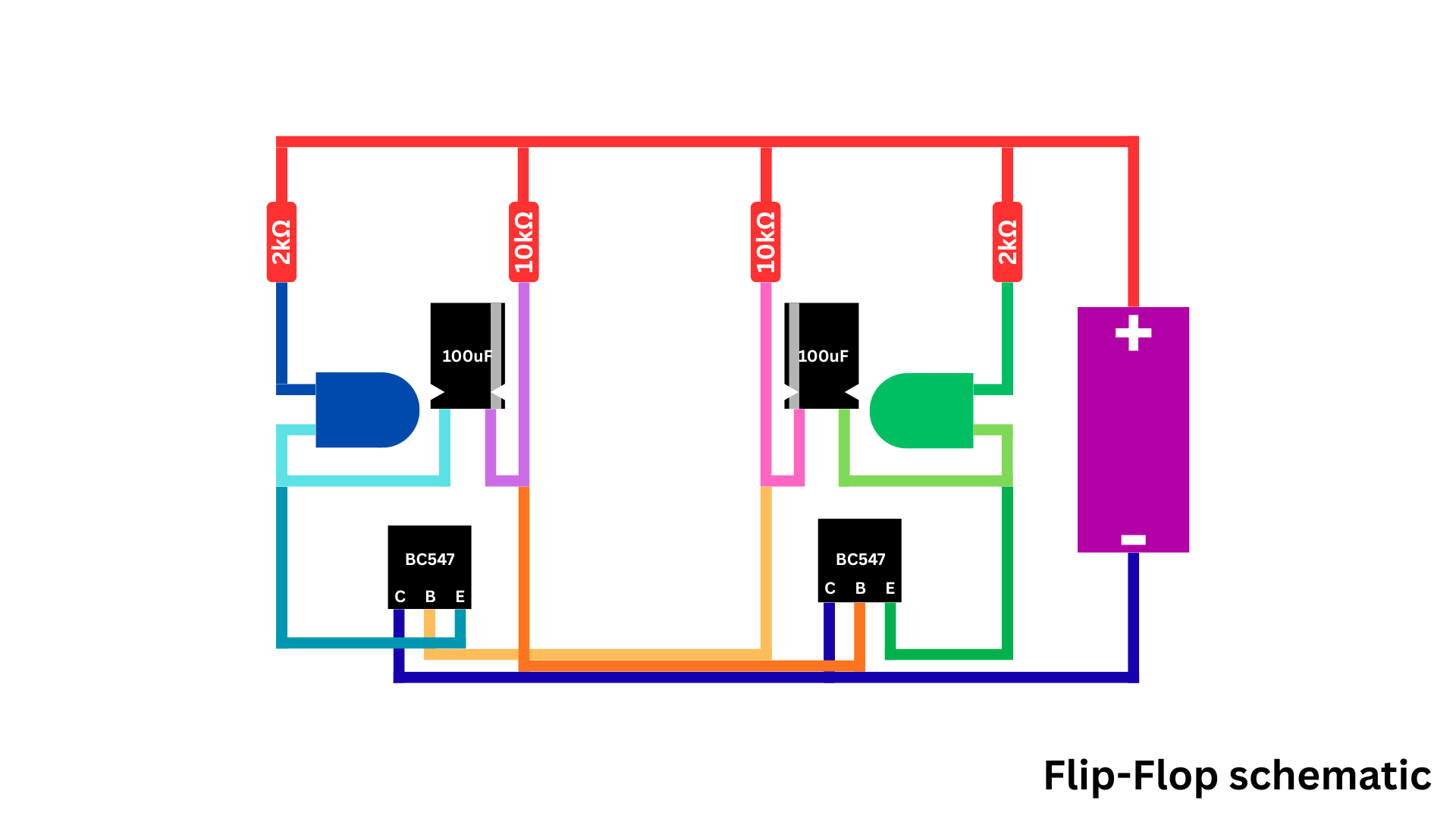
The first project was simple. Now let’s build something more interesting: a flip-flop. A circuit that makes two LEDs blink alternately when power is applied (see photo 1, 2, and 3).
What Is a Flip-Flop?
A flip-flop is one of the most fundamental circuits in digital electronics. It is a bistable system, meaning it has two stable states. Once it enters one state, it will remain there until an input causes it to change.
Each flip-flop stores exactly one bit of information. All digital memory systems, whether in old computers or modern processors, are ultimately composed of massive networks of such circuits.
In our design, two transistors, capacitors, and resistors form a simple oscillating flip-flop. Each transistor alternately turns the other off and on, creating the blinking effect. While this may appear simple, the same logic forms the basis of clocks, counters, and memory registers.
Step-by-Step Project
To create this project, you'll need:
- 2 × BC547 transistors
- 2 × 5mm LEDs
- 2 × 100 µF electrolytic capacitors
- 2 × 10 kΩ resistors
- 2 × 2 kΩ resistors
- 1 × 9V battery connector
To accomplish this project, I designed the circuit using KiCad, a free and professional-grade PCB design tool.
First, the schematic was created. Then it was converted into a board layout where the components are arranged and traces are routed.
Once the design was complete, I used the permanent marker (pen) to draw it on the copper, according to the schematic below. Then I went to manufacuring it, but the first PCB didn’t work quite well.
Some traces were faulty, so I decided to create another PCB. After some time and hard work, I finally got a PCB suitable for the project.
I cleaned it, drilled the holes and soldered the components.
Lastly, I connected the battery and watched the LEDs blinking one after the other.
Drawing traces by hand works well for simple designs but fails when circuits become more complex.
As complexity increases:
- Mistakes become more likely
- Spacing is harder to control
- Routing accuracy drops
For advanced projects, I recommend you use professional PCB manufacturing services.
Today, you learned not just how PCBs are made, but why they matter.
Even with minimal tools and inexpensive materials, it's possible to manufacture real, functional printed circuit boards at home.
If you want to take electronics seriously, PCB fabrication is not optional knowledge. It's a foundational skill that opens the door to better designs and more professional-level projects.
Additionally, if you enjoyed reading this article, you'll probably like this one as well, where I walk you through building an 8×8 LED matrix. Even better, you'll learn how to have the PCB manufactured in a real factory, just like professional electronics products.
Thanks for reading and happy building!


Comments