


Hardware components | ||||||
| × | 1 | ||||
| × | 1 | ||||
| × | 1 | ||||
 |
| × | 1 | |||
_ztBMuBhMHo.jpg?auto=compress%2Cformat&w=48&h=48&fit=fill&bg=ffffff) |
| × | 1 | |||
 |
| × | 1 | |||
Software apps and online services | ||||||
 |
| |||||
I've recently posted a tutorial about this project on YouTube explaining everything you can read on this article. You can watch it right below.
IntroductionHave you ever walked into a room where the lights turned on automatically as it got dark? Or maybe you’ve seen a robot following a black line on the floor with perfect precision. Behind both of these tricks is a simple but powerful component: the light sensor.
In this tutorial, we’ll explore what light sensors are, how they work, and then we’ll build a project where an LED automatically turns on in the dark.
This article is part of my Arduino for Beginners series (lesson #10 out of 24). If you’re new here, you can check out the previous lessons to catch up on concepts like resistance and potentiometers, we’ll build on that knowledge today.
How Light Sensors WorkThe light sensor we’ll use today is called a photoresistor or LDR (Light Dependent Resistor). Its resistance changes depending on how much light hits it:
- More light → lower resistance.
- Less light → higher resistance.
Think of it as an automatic potentiometer. Instead of turning a knob by hand, light itself controls the resistance.
If you followed lesson #9 (potentiometers), this will feel very familiar. Back then, we adjusted resistance manually. With a photoresistor, the environment is in control.
But there are other ways to detect light:
- Photodiodes: very fast, used in remotes and light detection circuits.
- Phototransistors: act like switches triggered by light.
- Digital light sensors: more precise, giving lux readings directly.
Photoresistors remain the easiest and cheapest option for beginners, which is why we’re starting here.
If you want to dive deeper into the semiconductor science behind photoresistors, this article gives you a great introduction to it.
SponsorThis lesson is made possible thanks to DFRobot.
DFRobot is a global provider of maker electronics, from simple sensors to powerful single-board computers.
They kindly sent me the MindPlus Arduino Coding Kit, which contains everything needed to follow along with this series: Arduino board, I/O expansion shield, LEDs, sensors, and more.
If you want to recreate these projects at home, check out DFRobot’s online store. They ship worldwide, and their components are affordable and reliable.
Thanks again to DFRobot for supporting this series and making STEM education accessible to everyone.
Project - Automatic LED Light Controller
Today’s project is a light-controlled LED system. The idea is simple:
- When it’s dark, the LED will automatically turn on.
- When there’s light, the LED will turn off.
This is basically the same principle used in those outdoor garden lamps that glow at night and recharge in the daytime.
Now let’s get our hands dirty and buity this project.
For this project, grab your MindPlus Arduino Coding Kit and pick out:
- Arduino board.
- I/O expansion shield.
- Red LED module.
- Analog ambient light sensor.
- Some jumper wires.
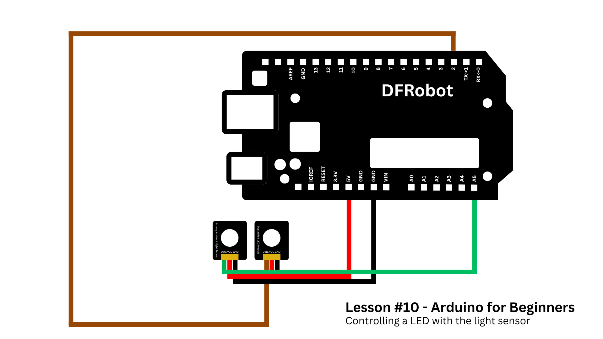
Assembly is straightforward:
- Attach the expansion shield to the Arduino.
- Connect the LED module to digital pin 2.
- Connect the photoresistor to analog pin A5.
That’s it for hardware. You can check the schematics below to help you wire everything right.
Now let’s program our project.
You can grab the full code from the GitHub repository for this series. Here’s the explanation of this sketch.
We start by defining our variables and telling the Arduino which pins we’re using. Nothing new here - you’ve done this in previous lessons.
int ledPin = 2;
int sensorPin = A5;
int sensorValue = 0;
int threshold = 500;

void setup() {
  pinMode(ledPin, OUTPUT);
  pinMode(sensorPin, INPUT);
  Serial.begin(9600);
}
In the loop(), we use analogRead() to get the sensor’s value. This gives us a number between 0 and 1023.
- Closer to 0 means dark.
- Closer to 1023 means bright light.
Remember, this is the exact same concept we saw in the potentiometer lesson - but now the knob is replaced by light levels.
sensorValue = analogRead(sensorPin);We then compare this value to a threshold - say 500.
- If the reading is below 500, it’s dark, so the LED turns on.
- If it’s above 500, there’s enough light, so the LED turns off.
if (sensorValue < threshold) {
  digitalWrite(ledPin, HIGH);
} else {
  digitalWrite(ledPin, LOW);
}Here’s the fun part: you can experiment with that threshold. If your room is very bright, 500 might be too low, so you can try 700 instead.
This is a great exercise in calibration, which is something you’ll do all the time in real-world electronics.
And that’s it. You now have a working automatic light controller.
ConclusionThat wraps up lesson #10! Today you learned:
- What a photoresistor is.
- How it works.
- And how to build a simple light-controlled LED system with Arduino.
In the next lesson, we’ll explore another input device: the sound sensor.
Until then, check out my previous tutorials if you want to strengthen your foundations.
Thanks for following along and happy making!


Comments