


Hardware components | ||||||
_ztBMuBhMHo.jpg?auto=compress%2Cformat&w=48&h=48&fit=fill&bg=ffffff) |
| × | 2 | |||
| × | 2 | ||||
 |
| × | 2 | |||
 |
| × | 2 | |||
| × | 6 | ||||
 |
| × | 2 | |||
 |
| × | 1 | |||
 |
| × | 1 | |||
Software apps and online services | ||||||
 |
| |||||
I've recently posted a tutorial about this project on YouTube explaining everything you can read on this article. You can watch it right below.
IntroductionLoRa is one of the most exciting wireless technologies available to makers today. With just a tiny module and an Arduino, you can send data across kilometers - without Wi-Fi, without a SIM card, and with barely any power consumption.
In this tutorial, you’ll learn how to use the RYLR993 Lite LoRa module with Arduino, how to configure it using AT commands, and how to build a practical two-way communication system where pressing a button on one board controls an LED on another (completely wirelessly).
Whether you're a beginner exploring LoRa for the first time or an Arduino user wanting to expand into long-range communication, this tutorial will guide you step-by-step through theory, wiring, configuration, and code.
Before building anything, let’s quickly understand what makes LoRa so unique.
LoRa stands for Long Range. It’s a communication technology developed by Semtech to solve a very specific problem:
- How can small, low-power devices communicate across very long distances?
Traditional wireless options fall short:
- Wi-Fi works only within a house or room and drains a lot of power.
- Cellular networks cover long distances but require SIM cards, subscriptions, and even more energy.
- Bluetooth works only across a few meters in most cases.
But imagine you need to:
- Monitor soil moisture in a farm 2 km away.
- Record river levels in a remote village.
- Track air quality in a forest with no connectivity.
- Build smart-city sensors across large areas.
That’s where LoRa shines.
LoRa is designed to send small packets of data - like temperature, humidity, sensor readings, or GPS coordinates - across distances that can reach 10 km or more, depending on your antenna and terrain.
All while consuming very little energy.
This is why LoRa is used everywhere:
- Precision agriculture.
- Environmental monitoring.
- Smart cities.
- Industrial automation.
- Home automation.
When people talk about LoRa, there are two main layers:
- LoRa Transceivers: individual modules, like the RYLR993 Lite, that transmit and receive data directly.
- LoRaWAN Gateways: bigger devices that receive LoRa data from dozens or hundreds of nodes and route it to the Internet.
But in this project, we’ll focus on the simplest and most beginner-friendly setup: two modules talking directly to each other (point-to-point communication).
Special Thanks to ReyaxBefore we jump into the project, I want to give a huge thank you to Reyax for sponsoring this tutorial and providing the RYLR993 Lite modules I’m using here.
Reyax is a well-known manufacturer of IoT communication hardware - including LoRa modules, Wi-Fi and Bluetooth modules, GNSS receivers, cellular solutions, and more. Their products are widely used by makers, educators, and professionals because they’re:
- Reliable: they work consistently across different environments
- Easy to integrate: simple wiring, simple commands, and clear pinouts
- Well-documented: their datasheets and guides actually explain things
- Affordable: good performance without destroying your budget
And because Reyax has distributors worldwide, it’s usually pretty easy to get your hands on their modules no matter where you live.
If you want to explore more of what they offer, take a look at their product catalog on their website. They have a lot of interesting modules that are fun to build with.
And if you are interested in the module I'm using today, I can find it in the following online stores:
I highly recommend you check it out. Thank you again to Reyax for sponsoring this project and help making STEM education accessible to everyone.
Getting to Know the RYLR993 Lite ModuleThe RYLR993 Lite is a compact LoRa transceiver with five pins:
- VCC: power input (3.0–3.6V only)
- GND: ground
- TX: UART transmit
- RX: UART receive (max 3.6V!)
- RESET: hardware reset (optional)
A few important notes:
Power
The module runs ONLY on 3.0-3.6V. So don't connect it directly to 5V. It will damage the LoRa module.
The Arduino’s 3.3V pin is enough for simple demos, but because the module can draw up to 140 mA during transmission, larger projects should use a dedicated 3.3V regulator.
Logic Levels
The RX pin cannot accept 5V. So when connecting it to an Arduino board, you must use a voltage divider (three 5kΩ resistors work perfectly as we'll see later).
Reset Pin
The RESET pin can erase configurations, but we won’t use it in this project. Leave it unconnected.
With that out of the way, let’s move on to the fun part.
In this hands-on project, we’ll use two LoRa modules and two Arduinos to demonstrate full two-way wireless communication.
Here’s what the system does:
- Press a button on Board 1 → LED toggles on Board 2
- Press a button on Board 2 → LED toggles on Board 1
Both boards:
- Send messages
- Receive messages
- Parse commands
- Update their LED state
It’s simple, visual, and an excellent introduction to LoRa.
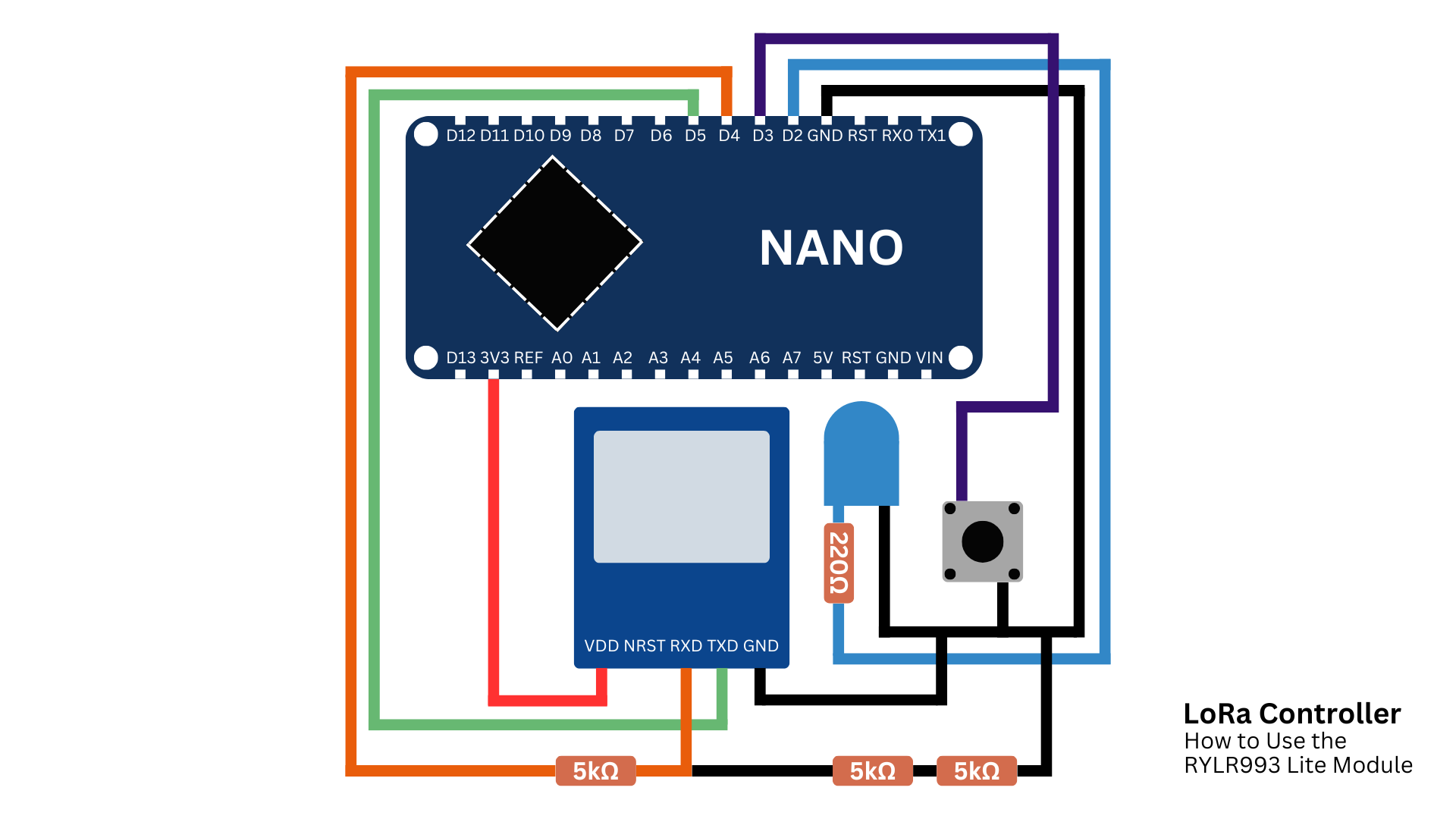
Wiring the HardwareEach board uses the same wiring.
1. Power
- RYLR993 VCC → Arduino 3.3V
- RYLR993 GND → Arduino GND
2. Communication
- Module TX → Arduino pin 5
- Module RX → Arduino pin 4 through a voltage divider (refer to the schematics below)
3. LED
- LED anode → 220Ω → Arduino pin 2
- LED cathode → GND
4. Button
- One leg → Arduino pin 3
- Other leg → GND
- Use Arduino’s internal pull-up resistor in software
Repeat this wiring for both boards, according to the following schematics.
In the end, you'll have something like this:
Before the modules can communicate, we must configure them.
Open the sketch set_up_lora from the project GitHub repository.
Upload it to your Arduino and open the Serial Monitor at 115200 baud.
Send this command first:
ATIf the module responds with OK, everything is wired correctly.
If not, double-check the wiring (TX, RX, power supply, etc).
Then, send the following command:
AT+OPMODE=1Mode 1 is Proprietary Mode, used for direct module-to-module communication. The default value is 0, and it's used for LoRaWAN networks.
Next, we need to define the frequency the module will operate. So, type:
AT+BAND=915000000915 MHz is used in countries like USA and Brazil. If you're in other parts of the world, your regional frequency may differ. Please check your local LoRa frequency and update this value accordingly.
Next, type this last command:
AT+ADDRESS=1The address is similar to an ID for the LoRa module. Each module in the same network must have a unique address.
After you send the following commands to the first board, disconnect it and connect the second one. The commands are the same, except for:
AT+ADDRESS=2As I mentioned earlier, each device must have a unique address.
Reyax provides a detailed AT Command Manual on their website (inside the Download tab) worth reading if you want to configure advanced features or explore what your LoRa module is capable of.
If you don't know how to use the Serial Monitor the right way, I have a tutorial all about that. Don’t forget to check it out.
Writing the Arduino CodeThe GitHub repository includes three sketches:
- set_up_lora - initial configuration
- device_1 - main code for board 1
- device_2 - same as board 1 but with a different address
Open the sketch device_1.
Here’s a breakdown of what it does.
This is the main sketch that runs on our Arduino.
At the top of the code, we define some constants and variables - the button pin, LED pin, and some helper variables to keep track of button states.
#include <SoftwareSerial.h>

const int blueLed = 2;
const int button = 3;
const int rx_pin = 4;
const int tx_pin = 5;
SoftwareSerial ReyaxLoRa(tx_pin, rx_pin);

bool ledState = false;
bool lastButtonState = HIGH;
In the setup() function, we start serial communication with both the LoRa module and the Serial Monitor. Then we automatically send a few AT commands to make sure the module is properly configured when the Arduino powers up.
ReyaxLoRa.println("AT");
delay(200);
ReyaxLoRa.println("AT+OPMODE=1");
delay(200);
ReyaxLoRa.println("AT+BAND=915000000");
delay(200);
ReyaxLoRa.println("AT+ADDRESS=1");
delay(200);
If you take closer attention, they are the same AT commands we sent in the previously sketch. You now be wondering:
- Why sending them by hand if we could have configured them through code since the beginning?
Well, I wanted you to write them down for two reasons:
- Firstly, to understand what AT commands are and how to use them manually.
- Second, to realize the need for automating this task as typing commands one by one isn’t practical for larger projects.
Moving on, in the loop() function, we have the main logic:
- First, we check if the button is pressed. If it is, we send a small text message through the LoRa module to the other board.
- Then, we check if our module has received any messages. If it has, we read it, verify where it came from, the sender, and if everything is right, then change the LED state - turning it on if it was off, or off if it was on.
If you’re having trouble understanding this sketch or wish to code with confidence, I have a tutorial all about Arduino programming. Don't forget to check it out.
Uploading and TestingUpload:
- device_1 to board 1
- device_2 to board 2
Power both boards.
Now press the button on one board - the LED on the other should toggle instantly.
Congratulations!
You’ve just built a two-way LoRa communication system.
If you enjoyed this project, I’ve got something exciting coming soon.
I’m preparing a masterclass on how to build your own Arduino-powered drone from scratch!
This upcoming course won’t be for complete beginners as we’ll dive into:
- Flight control systems
- Wireless communication
- PCB design
- 3D printing and mechanical structure
- And much more.
By the end, you’ll have a working drone you can actually fly - and a solid understanding of how it works from the inside out.
If that sounds like something you’d love to build, join the waiting list to be notified when enrollment opens.
What's Next?LoRa opens the door to a whole world of long-range IoT experiments. With this foundation, you can now build:
- Weather stations
- Precision agriculture solutions
- River level monitoring
- Smart home automation across large distances
- Wild life monitoring systems
Thank you so much for reading this article. If you enjoyed it, you'll also like this another one where I talk about how to leverage AI to predict air quality from landscape photos.


_3u05Tpwasz.png?auto=compress%2Cformat&w=40&h=40&fit=fillmax&bg=fff&dpr=2)
Comments