

Hardware components | ||||||
 |
| × | 1 | |||
Software apps and online services | ||||||
| ||||||
Xilinx's Vivado FPGA development tool possess some handy features, and one of my favorites is the design flow of the block design. The block design in Vivado is a graphic representation of working with RTL modules in the form of IP blocks (intellectual property blocks). The handy thing about working with RTL modules in the block design is that it will auto-detect certain types of reserved signals such as clocks, resets, and bus interfaces. It will then offer connection automation based upon these detections of reserved signals. It can then automatically connect IP blocks (RTL modules) with the correct clocking/reset structure.
There is a large catalog of prebuilt IP blocks included in Vivado that can be added to the block design, ranging from the IP blocks to instantiate a processor in the design, to GPIO controllers, memory/block RAM generators, and so on. The interface bus these IP blocks use for communication is AXI AMBA.
Now you probably have some of your own RTL modules you will want to use in the block design of Vivado. They can be added directly by right-clicking anywhere blank space in the block design window and selecting Add Module... but this means you'd have to code an AXI interface in it by hand if you wanted it to communicate on the AXI bus. I've done this in the past for simple implementations of AXI (see here), but would be daunting for anything past the most simple version of AXI, especially if I needed control of it from the embedded software running on the processor in the design.
To overcome this obstacle, Vivado provides a built-in IP packaging editor tool which generates the framework for an AXI IP block and you to simply insert your own RTL into it. This will also create the hooks and sources files for you to write the code to write/read data to the IP block in Vitis.
Since I've written an AXI interface by hand for a custom FIR filter to use in the block design in the past, I though it'd be a good example to take that same FIR RTL code and add the AXI interface using the built-in IP packaging editor tool in Vivado. So to demonstrate the overall flow of how to create and package your own AXI IP blocks, I'll be creating a basic project targeting the SP701 board (you could use any Xilinx FPGA Board you prefer though), launching the IP packaging editor tool and creating my AXI FIR IP block, then returning to the main Vivado project to add AXI FIR IP block to the block design, then running a testbench to verify its functionality.
Create Vivado ProjectFirst, launch Vivado and create a new project for the SP701. I'm currently using Vivado v2021.2 and this design flow is the same for v2021.1.
Starting from the blank new project, I created a new block design.
I made this design simple by just adding the MicroBlaze soft processor and applying the board presets. Working from BRAM is sufficient for this project so I didn't bother to instantiate and configure the memory interface generator for the DDR on the board.
Select the Add IP option and search for MicroBlaze, add it to the block design and run the resultant Block Automation that pops up in the green banner at the top of the window. I always like to include the interrupt controller as well in the board preset application.
Run connection automation only for the clocking wizard (clk_wiz) then manually connect the reset controller's (rst_clk_wiz) external reset (ext_reset_in) to the reset input pin.
Validate (check box icon) and save the block design, we'll return to it after creating the AXI FIR IP.
Create New AXI4 PeripheralTo create a new AXI peripheral using your own RTL and package as an IP block for use in the block design to take advantage of the automation features in the block design, select the Tools > Create and Package New IP...
In the resultant pop-up window step through the screens as prompted, selecting the option for Create AXI4 Peripheral, specifying the desired name for the IP block, location directory, and the number of AXI interfaces you IP block will have as well as the AXI type.
There are three main types of AXI utilized in Vivado:
- AXI4 (full)
- AXI4-Lite (see example here)
- AXI4-Stream
Each type suits different use cases better, in the case of this project I'm creating my own AXI FIR filter IP block. Since a FIR filter is being fed in and outputting a constant flow of data with known packet boundaries and flow control requirements, AXI4-Stream is the best suited type. It will require one slave interface to input data samples to and one master interface to output the processed samples on.
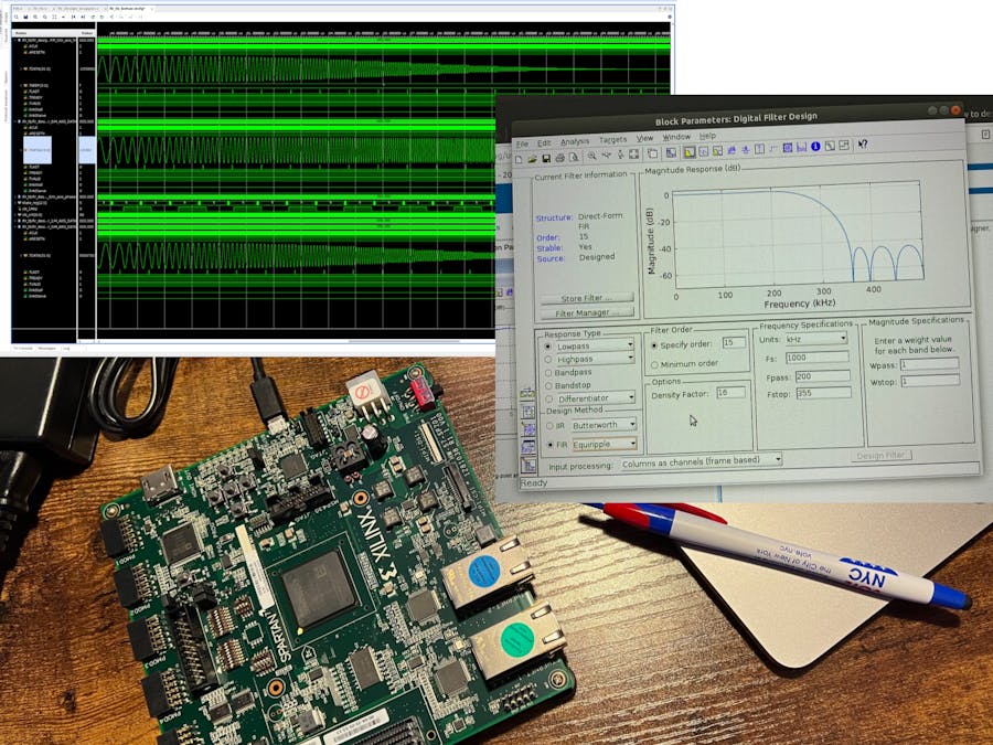
For reference, the FIR is a LPF running at 100 MS/s with 15 taps that takes in signed 16-bit data and outputs signed 32-bit data. It has a passband from from 1MHz - 10MHz and a stopband starting at 20MHz.
The final screen will give the option to launch the IP editor Vivado project (which is different from a regular Vivado project). Select Edit IP and click Finish. The main Vivado project just created targeting the SP701 will remain open and the IP Package editing Vivado project will open.
To start off in the IP editor Vivado project, I added my FIR Verilog file by selecting Add Sources from the Flow Navigator.
After pointing to my FIR Verilog file with the Add Files option, I found that it's important to uncheck the box to Scan and add RTL include files into project. Since this is not a normal Vivado project and the Verilog code is being packaged into an IP block, this option will throw errors.
Once added, the Sources hierarchy updates and the FIR Verilog file appears independently of the AXI Verilog source files (note: this is all in Verilog because I had the settings of the main Vivado project targeting the SP701 set to Verilog).
There are three RTL source files generated for this AXI4-Stream peripheral per the selections made when generating the IP editor Vivado project:
- The slave interface functionality RTL.
- The master interface functionality RTL.
- The top level wrapper with physical interface declarations and instantiations of the master and slave interfaces.
And of course there is my custom FIR RTL that I imported as a design source. I am instantiating this also in the top level wrapper of the AXI peripheral such that streaming data comes in on the slave AXI interface, is passed through the FIR RTL, then streamed out of the master AXI interface.
Before adding that however, a couple of optional AXI4-Stream interface signals that aren’t enabled by default need to be added to both the master and slave AXI ports. Most DSP IP blocks such as the DDS compiler (which I‘m going to use to feed the FIR for verification/demonstration purposes) utilize the extra AXI4-Stream signals of keep and tlast.
Adding these optional signals is straightforward, but not clear initially. Navigate to the Customization Parameters tab in the Package IP window.
Both the master and slave interfaces need tkeep added to them, so right-click on each and select Edit Interface.
Enable HAS_TKEEP in Parameters tab by clicking on each then clicking the single arrow to move it from the left column to the right column.
Then switch to the Port Mapping tab to map tkeep and tlast to the AXI IP block's physical interface. Match the tkeep and tlast signals to each other respectively in the Interface’s Logical Ports column and IP’s Physical Ports column. Then verify they mapping in the Mapped Ports Summary column below.
Since tkeep isn’t enabled by default, its port declarations also have to be manually added to the user-defined port declaration sections of all three AXI interface RTL source files (marked by Users to add ports here comments). It also needs to be added to the AXI master and slave interface instantiations in the top level AXI wrapper.
Instantiate the FIR Verilog module in the section marked by the comment Add user logic here.
Now while the basic functionality of the AXI interfaces is automatically generated in each of the RTL source files respectively, the logic of how the data is extracted from the input data stream and passed into your own custom logic is up to you to define. As well as how the data output from your custom logic is fed into the master AXI interface to output. Thus, you’ll notice the same Add user logic here in each of the three autogenerated RTL source files.
The other thing to note is that the functionality of the AXI4-Stream interface requires some modifications to add the tkeep and tlast signal functionality to the master and slave AXI interfaces.
Another unique aspect of this project if that I had to also tweak the slave interface to keep tready from deasserting for one clock cycle between data packets because the DDS compiler will drop samples output on its master AXI interface every time that the connect slave interface‘s tready goes low.
The final unique requirement in this project is that because the core of this logic is a FIR filter, both the master and slave AXI interfaces and the FIR need to be clocked by the same clock that is the FIR sampling clock (unless you want to get deep into the weeds of clock crossing domains to preserve the data rate on both the master and slave interfaces). So I just passed the slave AXI interface clock to the FIR and master AXI instantiations.
Returning to the Package IP window, let’s go through each of the tabs and validate the settings to then finally package it up.
In the first tab is basic display information to the output AXI peripheral IP package.
The second tab is important not to forget. By default, the AXI peripheral IP only includes support for whichever FPGA chip family was targeted by the main Vivado that the IP package editor was launched from (the Spartan 7 in this case since the main Vivado project targets the SP701). A majority of the time, you’ll probably want to be able to use your AXI peripheral IP block with other Xilinx FPGA chip families
Add support for all target FPGA chip families, select the + button and check the box for All Families and Parts then click OK.
You can click through the rest of the tabs, simply validating the selections already made, but skipping the Addressing and Memory tab since there is no data conversion from stream to memory map to place values in memory.
In the final tab, click the Package IP button at the bottom of the window (it will say Re-Package IP if you come back to edit and repackage in the future). A prompt will appear asking if you’d like to close the IP editor Vivado project.
At this point the FIR AXI IP block is packaged and placed in a repository in the directory specified the first tab of the Package IP window.
Add Custom AXI4-Stream FIR to Block DiagramNow that the custom FIR AXI IP block has been completed and package, we can return back to the original Vivado project to add it to the block design.
Since the IP package editor was launched from this Vivado project, the repository the AXI FIR was output too is automatically added to the main Vivado project. However, if you want to use you custom AXI IP blocks in other projects, you’ll need to add its repository to the respective Vivado project. Select Settings from the Flow Navigator > IP > Repository > +. Then point to the AXI IP repository.
In the block design I’ll be adding my AXI FIR IP the same way I added the MicroBlaze IP block. I’m also adding a DDS compiler IP block to stream data into the FIR to test it.
I also imported the custom controller state machine I have to control the DDS compiler into the block design by adding it as a module (right-click in blank space in the block design window and select Add Module…), as well as my memory dump Verilog module that simply as an AXI slave always ready to receive data from the FIR‘s master AXI interface. I attached all source files below if you’d like to use them for your own testing.
Here’s the final block design:
Rerun validation and save then create a top level HDL wrapper for the block design by right-clicking on the block design file in the Sources window and selecting Create HDL Wrapper… option. Leave the option to let Vivado manage the wrapper file checked.
So to verify/demonstrate the functionality of the AXIS FIR, it is being streamed data from a DDS compiler that is outputting a chirp signal from 1 MHz - 25 MHz. Which should come out of the FIR unattenuated from 1 MHz - 10 MHz then proportionally decrease through the transition band of the FIR until it hits 20 MHz, at which point the AXIS FIR should be attenuating the output to zero.
The phase increment state machine controlling the DDS compiler is simply looping through feeding the DDS the phase increment values for 1MHz - 25MHz in 1MHz increments. And the memory dump module is simply pulling the samples out of the FIR and just throwing them away. This is all for the sake of getting the FIR to run in a behavioral simulation so that we can see it allow the first 10MHz of signal pass through unattenuated, then start to be attenuated until it‘s fully suppressed after 20MHz.
Create TestbenchTo create a testbench file in Vivado, click Add Sources from the Flow Navigator and select the option to Add or create simulation sources then give the testbench file the desired name.
Once the testbench file is generated and appears in the Sources tab under the sim folder, right-click on it and select Set as Top.
In this case just the block design needs to be instantiated in the block design and the differential system clock and main FPGA reset supplied to it. My phase increment state machine takes care of running everything on its own once it receives a clock and reset signal.
`timescale 1ns / 1ps

module sp701_bd_tb;

    reg clk_p, clk_n, reset;

    always begin
        clk_p = 1; clk_n = 0; #5;
        clk_p = 0; clk_n = 1; #5;
    end

    always begin
        reset = 1; #40;
        reset = 0; #1000000000;
    end

    sp701_bd sp701_bd_i (
        .reset(reset),
        .sys_diff_clock_clk_n(clk_p),
        .sys_diff_clock_clk_p(clk_n)
    );

endmodule
I found that while not needed in a synthesized and placed & routed design, AXI interface output signals such and tlast, tvalid, and tdata on a master interface must be initialized to something. Otherwise the simulation won't run and throw a very vague error that's impossible to interpret without a fair amount of time spent on Google.
Click Run Simulation in the Flow Navigator window and select Run Behavioral Simulation (which is the only option since we haven’t run synthesis, implementation, or generated a bitstream).
Run Behavioral SimulationWhen the simulation launches, only the main system clock and reset signals will appear in the waveform window. Select the desired signals to view from the Scope column, right-click on each, and select Add to Wave Window.
I added the master tdata signals output from the DDS compiler and AXI FIR filter. To easily view if the functionality is correct, right click on each of these tdata signals in the Wave Window and change the Radix from Hex to Signed Decimal and the Waveform Style from Digital to Analog.
And there it is! We can see that the FIR is indeed successfully working as a low pass filter as intended.
Side Note: attempting to add an ILA to view the FIR’s output signal will insert logic that messes with the timing and sampling of the FIR causing the FIR not to work anymore and it simply passes through any waveform presented to it.


Comments