


Hardware components | ||||||
| × | 1 | ||||
| × | 1 | ||||
| × | 1 | ||||
Software apps and online services | ||||||
| ||||||
| ||||||
Welcome to this hands-on tutorial on setting up basic RF reception using the ADRV9009 wideband transceiver mounted on the ZCU102 evaluation board, all controlled through GNU Radio.
The ADRV9009 is one of the most capable RF agile transceivers available today: dual RX / dual TX channels, instantaneous bandwidths up to 200 MHz, operating range ~75 MHz–6 GHz, excellent phase coherence, and support for advanced MIMO and beamforming concepts. When paired with the powerful Zynq UltraScale+ MPSoC on the ZCU102, you get a flexible, high-performance SDR platform ready for serious prototyping.
While Analog Devices provides polished evaluation tools (IIO Oscilloscope, TES GUI, pre-built profiles) that are perfect for quick bring-up and datasheet validation ✅, many engineers and researchers prefer GNU Radio for its openness and flexibility.
GNU Radio lets you:
- Build fully custom signal processing chains visually 🧩
- Integrate the ADRV9009 natively via the gr-iio blocks
- Run flow graphs locally on the ZCU102 or remotely from a host PC
- Easily extend to demodulation, multi-channel capture, real-time analysis, file recording, or your own out-of-tree modules
This tutorial focuses on the essentials: getting clean IQ samples from the ADRV9009 RX path into a GNU Radio flow graph so you can see and work with live RF signals.
By the end, you’ll have a working receive chain showing spectrum and time-domain views — the foundation for almost any SDR experiment you want to build next.
Let’s get started. 🚀
Step 1: Prepare and Boot the ADI Kuiper Linux Image on an SD Card 🛠️
To get the ZCU102 up and running with the ADRV9009, the first and most reliable step is to boot the official Analog Devices Kuiper Linux image. This distribution includes the necessary IIO drivers, device trees, and HDL bitstreams pre-configured for ADI hardware like the ADRV9009 on ZCU102.
Kuiper Linux provides a solid foundation for GNU Radio integration via gr-iio, ensuring the ADRV9009 is properly detected as an IIO device.
Why Use the ADI Kuiper Image?
- It bundles Linux kernel drivers for the ADRV9009 (via libiio).
- It includes the correct device tree overlays and boot files for ZCU102 + ADRV9009.
- It's regularly updated and widely tested by the ADI community.
- For basic reception, this avoids custom PetaLinux builds at the start.
What You'll Need
- A microSD card (16 GB or larger recommended; Class 10 or better).
- A computer with an SD card reader/writer.
- Internet access to download the image.
Step-by-Step Guide
1.Download the Latest ADI Kuiper Linux ImageHead to the official Analog Devices resources:
- Main release notes and download links: https://wiki.analog.com/resources/tools-software/linux-software/adi-kuiper_images/release_notes
- Pre-built images are available via GitHub Actions workflows: https://github.com/analogdevicesinc/adi-kuiper-gen/actions/workflows/kuiper2_0-build.ymlLook for the most recent successful run (check the green checkmarks), then download the full image (e.g., something like 202X-XX-XX-ADI-Kuiper-full.img.xz or similar).
- For ZCU102 + ADRV9009 specifically, confirm support in the project list: https://wiki.analog.com/resources/tools-software/linux-software/kuiper-linux/project-list (search for zynqmp-zcu102-rev10-adrv9009 or similar entries).
Download and decompress the.img.xz file (use 7-Zip on Windows, unxz on Linux, or similar) to get the raw.img file.
2.Write the Image to the SD Card: Use a reliable tool to flash the image (this erases the entire card):
- Windows: Balena Etcher (recommended) or Win32 Disk Imager.Select the.img file → choose your SD card → Flash/Write. Ignore any "validation error" at the end with Etcher—it's often harmless if the write completed.
- Linux/macOS: Use dd (be very careful with the device name!):
sudo dd if=your-image.img of=/dev/sdX bs=4M status=progress conv=fsync3.Customize the Boot Files: This setup require copying project-specific files from the ADI HDL reference design or project folders.
- After flashing the base image, the SD card has a FAT32 BOOT partition.
For ADRV9009 on ZCU102, you may need to replace/update:
- BOOT.BIN (FPGA bitstream + FSBL + PMUFW)
- Image (kernel)
- system.dtb (device tree blob)
BOOT.BIN and system.dtb will be found in BOOT partition in folder zynqmp-zcu102-rev10-adrv9009 while Image.ui will be found in zynq-common folder copy these files and paste into root of BOOT partition.
Step 2: Configure the ZCU102 for SD Boot🛠️
- Power off the ZCU102 with ADRV9009 mounted on HPC1 FMC card.
- Set the boot mode switches (SW6): Typical for SD boot: 1: OFF, 2: OFF, 3: OFF, 4: ON (check ZCU102 user guide or silkscreen for exact Rev 1.0/1.1 config).
- Insert the prepared SD card into the slot (J100).
- Connect UART (micro-USB to J83) for console output (115200 baud, 8N1). I am using PuTTy. If you want to know how to set PuTTy up refer to my below tutotrial Setting Up PuTTy Section: https://www.hackster.io/saqibsherawan/signal-transmission-and-reception-using-adrv9009-zcu102-b4d7aa#toc-step-9--setting-up-putty-11
- Connect Power
- Connect Ethernet Cable one side to your ZCU102 other to your host computer
Step 3 : Power on and Verify Boot🛠️
- Power up the board.
- Watch the UART console (use PuTTY, minicom, or screen).
- You should see U-Boot messages, then kernel boot, ending at a login prompt (default: root / analog).
- LEDs: DONE LED should light up; no red error LEDs as shown in Figure 4.
- Once logged in, run:
iio_attr -c adrv9009-phyto confirm ADRV9009 is detected as shown in Figure 5
Troubleshooting Tips
- No output? Double-check SW6 switches and UART connection.
- Boot hangs? Try a different SD card or re-flash.
- HDMI not working? Common on some images—use UART or SSH instead.
- For latest issues, check EngineerZone forums (search "ZCU102 ADRV9009 Kuiper").
Step 4 : Install GNU Radio and Required Libraries on Your Host PC 🖥️
Prerequisites
- Ubuntu 22.04 LTS or 24.04 LTS (recommended; 20.04 is older but still works with tweaks).
- Internet access.
- sudo privileges.
Download and build libiio
Libiio requires the following packages:
- libxml2
- libxml2-dev
- bison
- flex
- cmake
- git
- libaio-dev
Install with apt:
(sudo) apt install libxml2 libxml2-dev bison flex cmake git libaio-dev libboost-all-devIf you want the documentation for the C API you will require doxygen:
(sudo) apt install doxygenIf you want the USB backend add libusb support:
(sudo) apt install libusb-1.0-0-devIf you want zeroconf add avahi support:
(sudo) apt install libavahi-common-dev libavahi-client-devBuild and install libiio from source:
git clone https://github.com/analogdevicesinc/libiio.git -b v0.25
cd libiio
mkdir build
cd build
cmake .. -DPYTHON_BINDINGS=ON
make
sudo make install
cd ../..
Next Install GNU Radio the latest version from the official site. Recommended approach is given below
Recommended Approach (2026 Context)
- Use GNU Radio 3.10 or newer — gr-iio is fully integrated into mainline GNU Radio since 3.10, so no separate OOT module build is needed in most cases.
- Install via the official GNU Radio PPA for Ubuntu (easiest and most up-to-date).
- Build libiio from source (recommended by ADI for latest features and compatibility).
- Skip libad9361-iio (it's for AD936x family; ADRV9009 gneric libiio drivers).
Step 5: Configure Static IP Addresses for Direct Ethernet Connection 🌐
To enable reliable remote access from your host PC to the ZCU102 (for streaming IQ samples via gr-iio / libiio over the network), we'll set up a point-to-point Ethernet link using a static IP subnet.
Common convention for ADI boards
- ZCU102 (target): 192.168.2.1/24
- Host PC: 192.168.2.10/24 (or any unused address in 192.168.2.0/24 except.1 and.254)
This avoids DHCP issues and ensures low-latency, high-throughput communication — essential for sample rates > 50 MSPS.
Important Notes Before Starting
- Use a direct Ethernet cable between your host PC's Ethernet port and the ZCU102's Ethernet port (J100, RJ45 on the board).
- No router/switch needed (unless you add a gateway later).
- These changes are temporary (until reboot). For persistence, edit network config files on the ZCU102 (e.g., /etc/systemd/network/ or use enable_static_ip.sh if present in your Kuiper image).
- On the host, we'll use nmcli (NetworkManager CLI), common on Ubuntu desktops.
On the ZCU102 Side (via UART Console)
Log in as root (password: analog) and run these commands one by one:
Bash
# Flush any existing IP on eth0
ip addr flush dev eth0

# Assign static IP 192.168.2.1 with /24 subnet mask
ip addr add 192.168.2.1/24 dev eth0

# Bring the interface up
ip link set eth0 up

# (Optional) Add a default gateway if you need internet access via another interface/router
# Skip this if it's a direct PC-to-board cable
ip route add default via 192.168.2.254
Verify the configuration:
Bash
ip addr show eth0
# or the classic:
ifconfig eth0
Expected output snippet (as shown in Figure 6):
On the Host PC Side (Ubuntu)
Assuming your Ethernet interface is named enp7s0 (common on desktops; check with ip link or nmcli device to confirm — it might be enpXsY, eth0, etc.).
Run:
Bash
# Replace enp7s0 with your actual Ethernet interface name if different!
sudo nmcli connection modify enp7s0 \
    ipv4.method manual \
    ipv4.addresses 192.168.2.10/24 \
    ipv4.gateway "" \
    ipv4.dns "" \
    connection.autoconnect yes

# Bring the connection down and back up to apply changes
sudo nmcli connection down enp7s0
sudo nmcli connection up enp7s0
Verify:
Bash
ip addr show enp7s0
# or
ifconfig enp7s0
Expected output snippet (as shown in Figure 7):
Test Connectivity
From the host PC terminal:
Bash
ping 192.168.2.1- Success: You see replies like 64 bytes from 192.168.2.1: icmp_seq=1 ttl=64 time=0.5 ms
- Failure? Check cable, interface names, firewall (sudo ufw allow from 192.168.2.0/24), or if eth0 is really up on the board.
From the ZCU102 console (optional reverse test):
Bash
ping 192.168.2.10Verify ADRV9009 Detection via IIO
From the host PC (now that network is up):
Bash
# Scan for IIO contexts (should show the board)
iio_info -s

# Or directly query the board
iio_info -u ip:192.168.2.1
Expected successful output includes lines like:
❗❗❗❗ Important Tip: If at any point your connection is lost it is happening because Ubuntu switches back to its default auto IP. Rerun the below command again and Repeat the step
sudo nmcli connection modify netplan-enp7s0 ipv4.method manual ipv4.addresses 192.168.2.10/24 ipv4.gateway "" ipv4.dns "" connection.autoconnect yesOr at minimum, no "No devices found" error and soit isme device listing.
You can also probe attributes:
Bash
iio_attr -u ip:192.168.2.1 -c adrv9009-phyIf you see the ADRV9009-phy device and its attributes (gain modes, frequencies, etc.), congratulations — the network link is solid and the transceiver is visible remotely! This is the key prerequisite for GNU Radio flow graphs using the IIO Device Source block with URI ip:192.168.2.1.
Troubleshooting Quick Hits
- No ping? Double-check cable (use known-good Cat5e+), try swapping ends, ensure no other network conflicts.
- Interface name wrong? Run nmcli device status or ip link on host.
- iio_info fails? Rerun:
sudo nmcli connection modify netplan-enp7s0 ipv4.method manual ipv4.addresses 192.168.2.10/24 ipv4.gateway "" ipv4.dns "" connection.autoconnect yesEnsure libiio is installed/updated on host (from previous step).
- Firewall blocking? Temporarily sudo ufw disable to test (re-enable after).
- Board reboots lose IP? Change the IP again
Network is now configured — we're one step closer to seeing live RF in GNU Radio!
Step 6: Building a Basic GNU Radio Flow Graph for ADRV9009 RX 📊
With the network link working (ZCU102 at 192.168.2.1 visible via iio_info), and GNU Radio installed on your host PC, let's create your first simple receive flow graph in GNU Radio Companion (GRC).
This flow graph will:
- Use the IIO Device Source block to pull live IQ samples from the ADRV9009 RX path.
- Include basic conversion/processing to make the signal usable (e.g., handling complex samples).
- Display the received spectrum and time-domain waveform using QT GUI sinks.
Launch GNU Radio Companion
On your Ubuntu host:
text
gnuradio-companionCreate a new flow graph (File → New).
Key Blocks We'll Use
- IIO Device Source (under "Sources" or search "IIO") — this is the hardware input from ADRV9009.
- Short to FLoat and Float to Complex (under "Type Converters")
- QT GUI Sink
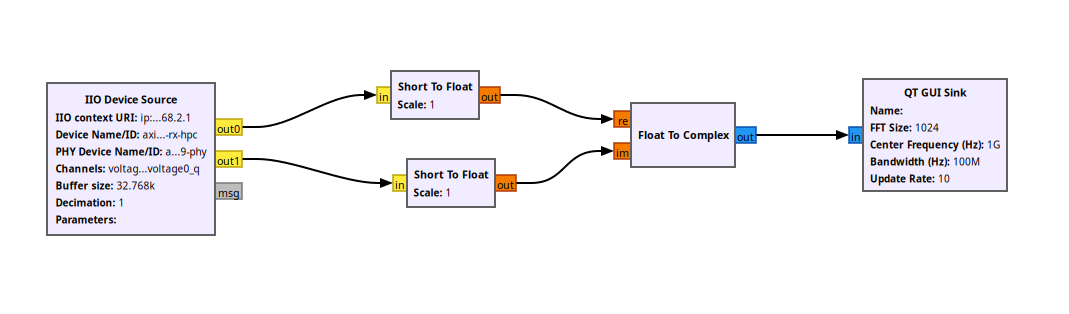
Step-by-Step: Build the Flow Graph
1.Add the IIO Device Source
Search for "IIO Device Source" in the block library (right panel) and drag it to the canvas.
Double-click to edit properties (important params for ADRV9009) and make them according to Figure 11
2. Add two Short to Float Blocks for I and Q and keep them in default configuration
3. Add a QT GUI Sink for time domain and Frequency domain view (Figure 12)
4. The Final Flow Graph will look as shown in Figure 13.
Final Step: Run and Enjoy Your Basic ADRV9009 RX Flow Graph 🎉
Now Connect Receive one port of your ADRV9009 to a signal source in my case I connected it to a signal of 1GHz using SynthUSB
In GNU Radio Companion:
- Save your file
- Press F5 (Generate)
- Press F6 (Execute)
What happens:
- QT GUI windows open (Frequency Sink + Time Sink)
- Live IQ samples stream from the ADRV9009 → spectrum and waveform update in real time
Play around:
- Watch for peaks, raised noise floors, or modulated signals
- Adjust gain if the plot is too noisy or clips
Success looks like:
- Waterfall scrolling with activity
- Spectrum showing visible signals when tuned correctly
- Time-domain waveform moving with real RF input
You've now got a working remote SDR receiver in GNU Radio — the foundation is complete!
Enjoy scanning the airwaves. 📡✨


Comments