

Hardware components | ||||||
 |
| × | 1 | |||
Software apps and online services | ||||||
| ||||||
We are in front of our customers, we have our design fully tested in our lab, all analog and digital filters works perfectly, but, in the customer installations there are an unknonw noise source. In this case, we must recompute digital filters, and spend time re sintesizing and implementing. Maybe this situation is a bit exaggerated, but there are a lot of situations where modify the characteristics of our filters in deployment phase may be very helpful.
Equations for compute the coefficients for digital filters, may be easy for low order FIR filters, or very complicated for several order IIR filters. Luckily, there are some tools that can kelp us to compute them. Most used tool for this purpose, surely is Matlab, but there are good open source alternatives like Octave or Python’s library Numpy and Scipy, and is the last one the way that I’ll show you in the next project using Pynq.
First of all, we need an IP with a filter, where the coefficients are sended through AXI. In 96analogxperience repository, you can find the IP axi_fir0_v1.0, that is a 8 order FIR filter with configurable coefficients through AXI interface. Input and output widths are configured when the IP is instantiated. Since the 96AnalogXperience works with 16 bits, we will use this width for input and output. INput and output signals, for this example will use Q15 format. For the coefficients, AXI provide us a efficient way to interchange parameter of 32 and 64 bits. IN this case, we will use parameters with 32 bits, this value is fixed inside the IP code, and we will configure the decimal at 31. Decimal width of parameters will depend of the paramaters, since if their values are in the range +-1, we can use only o bit for the integer part, but if the parameters have bigger values, the decimal part needs to be reconfigured.
In addition to the AXI filter, we will need some modules. First, we need a clock enable generator for generate a one clock cycle signal at desired frequency, cen_generator_v1_0, v, and a module where we will generate the signal that we will filter, signal_generator_v1_0.v. This last module, read signal values from BRAM infered. Values in BRAM are generated with a python script named mem_generator. This script is written for a jupyter notebook.
Once we have a block design complete, the nexts steps are generate the wrapper, and generate bitstream,.xdc and.hwh. All this files have to be copied in ultra96 through the samba server generated by Pynq.
Once we are connected to the jupyter notebook of Pynq, we can start to write code. First we have to add several libraries to the Python code.
from pynq import Overlay
import numpy as np
from scipy import signal
import matplotlib.pyplot as plt
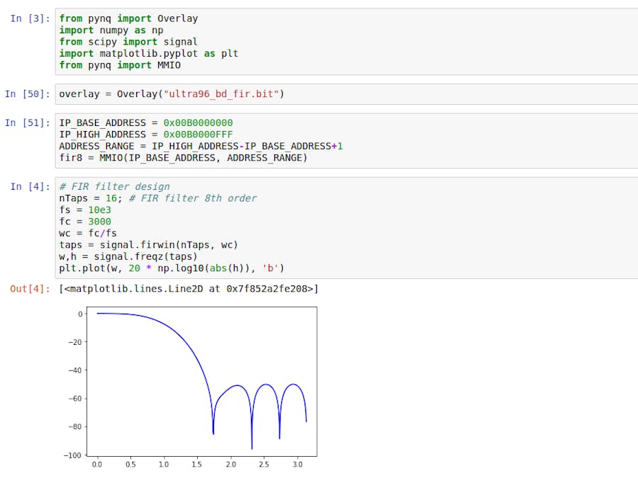
from pynq import MMIOOverlay is the librarie in charge of configure the PL with our design, LIbraries numpy and scipy are used to compute the fir filter coefficients, and operate with them. Matplolib is used to generate a graph of bode diagram, This is a fast way to verify the fir filter. And the last library that we have to import is MMIO. This library give us the possibility to "talk" with the fir IP. In this case, we will use the methods of the library to write coefficients in the IP.
Once all libraries are imported, we can design the fir filter. For that, we can use the method firwin.
# FIR filter design
nTaps = 8; # FIR filter 8th order
fs = 10e3/2 # This value is corresponding with the Nyquist frequency
fc = 3000
wc = fc/fs
taps = signal.firwin(nTaps,wc)
Notice that the order of the filter is defined in the IP, so this value must to be configured to 8. Sample frequency will depends of the constant connected to cen_generator, because the signal generated with this module will set the frequency of all discrete system. Fc is the cut frequency, and its value can be set from 0 to fs/2, or Nyquist frequency. Once the filter has to be defined, with the firwin methods we obtain the 9 coefficients needed for the FIR filter.
Cofficients computed are float, and the IP need a fixed point 32 bits values, so the next step is convert this float coefficients in Q31 format. Once we have the coefficients, we can send them to the IP with the MMIO methods.
# Write filter coefficients on IP
coeffIndex = 0
for j in tapsQ:
  fir8.write(coeffIndex,j)
  coeffIndex = coeffIndex+4
This design is designed to work in AVNET’s Ultra96 board, and my 96AnalogXperience. If you don’t know this mezzanine card, you can find the project on hackster.io. The Github repository includes a script for redraw the block design and configure all, but feel free to use the IP for modify or improve the design and, if you want, share it in the comments field. Below this lines, are the complete script for design the FIR filter, and configure the AXI IP through MMIO interface.
I hope you enjoy with this project. Thanks for reading!


Comments