

Hardware components | ||||||
| × | 1 | ||||
| × | 1 | ||||
| × | 1 | ||||
 |
| × | 1 | |||
 |
| × | 1 | |||
| × | 1 | ||||
| × | 1 | ||||
 |
| × | 1 | |||
Software apps and online services | ||||||
_4YUDWziWQ8.png?auto=compress%2Cformat&w=48&h=48&fit=fill&bg=ffffff) |
| |||||
| ||||||
Hand tools and fabrication machines | ||||||
 |
| |||||
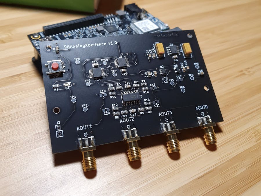
The 96AnalogXperience is a mezzanine board for Avnet's Ultra96. This board brings us 4 bipolar analog outputs from -2.5 to 2.5 volts, 16 bits of resolution, and maximum output current per channel up to 8mA. The DAC control signals are connected to the PL for allow high speeds. Even that, if you want to manage the DAC through the PS from a bare metal design, or even PYNQ, it is possible using the IP you can find in the repository.
Power supplies.Ultra96 board provide us 2 supplies, 5 volts with a maximun current for the entire kit of 6 amps, and 1v8 and 1 amp for the entire kit. 96AnalogXperience has an on board 3v3, 0, 5 amp regulator for DAC and 2.5 volts voltage reference.
Also, for allow negative voltage outputs, the board has a charge pump integrated circuit, a LM2662 of TI. Adding to this IC 2 capacitors with a value of 47uF, bring us an inverted output with the same level of the input.
It's important to notice that although ZynqUS+ is capable to manage in some banks voltages up to 3v3, the output voltage depends of the supply of this bank. In Ultra96 board, all banks accesibles on the expansion connectors are supplied with 1v8, so the max output we can obtain is 1v8. Is difficult to find a relative low cost DAC that allow a digital input so low, so we need to translate the output signals from the ZynqUS+ from 1v8 to 3v3.
For this mission, 96AnalogXpertience has one ADG3304. This is a bidirectional logic level translator that allow inputs/outputs from 1.15 volts up to 5.5. In the case of this board, we don't need the bidirectionality, but the IC has a competitive price, and allow data rates up to 50Mbps, so it's a good option for this design.
The most important element of the 96AnalogXperience is the DAC. In this board, I've choose a DAC80004. This DAC has 4 output channels, with 16 bits of resolution, and SPI inteface with a maximum clock of 25MHz at 3.3 volts, and 50Mhz at 5 volts.
The maximum analog data rate that DAC allow us can be computed adding communicatio time and the settling time. The setting time of DAC8000x can be found at page 6 of datasheet and can be up to 8us (25% to 75%). The communication delay can be computed according the next figure from datasheet.
We have to compute the next sum.
tw3+tsu+(tc*32)+td4 = 35ns+30ns+(40ns*32)+20=1.365us
So, the DAC is capable to bring to the output one data every 9.365us in the worst case, that is a output rate of 106kHz. This rate allow us to obtain a signal with a frequency up to 53kHz.
DAC also allow us set the initial voltage. In our case, the output is bipolar, so the the range is 2.5:-2.5, digitally talking, 0:2^16, and the zero output is centered in the middle of the range, at 2^15, and the middle of the range is available to set for the initial voltage through the pin POR.
One benefit of this DAC is that Texas Instruments has with the same package, ans same SPI protocol, options for 12 bits (DAC60004), and 14 bits (DAC70004).
Signal conditioning for the real world.Once we have the DAC output, this signal has values from 0 to 2.5 volts, and we want to translate this in -2.5 to 2.5, so the easiest way to do this, is the recommended circuit for this kind of applications.
The amplifier that I've choose is the LM324. Is cheaper, easy to find, and the frequency response is quite enough for this prototype.
Interface with Ultra96The interface with Ultra96 is made through low speed expansion connector.
It's important to notice that 96AnalogXperience board will remain over the power up button, so is necessary connect in parallel, between pin 4 and GND, a new power up button.
Testing capabilities.We are going to verify the settling time. In this case, we have to test this parameter without any external load. The first capture, show us how the settling time from 25% to 75% is less than 8us.
The second capture show us the settling time from 0% to 100%. Notice that in this case, the DAC has a strange shape when its output is arriving to 100%.
With this values we can estimate the maximum frequency that we can synthesize with this board. This maximum frequency will depends of the range of the signal. For signals between 25% and 75%, the first estimation of 53kHz may be accomplished, but we have to keep in mind that this rate only will be true with no load, or very low capacitance.
If you need more information about the 96AnalogXperience, feel free to contact me. pablo@controlpaths.com


_Ujn5WoVOOu.png?auto=compress%2Cformat&w=40&h=40&fit=fillmax&bg=fff&dpr=2)


Comments