


Hardware components | ||||||
| × | 1 | ||||
| × | 1 | ||||
| × | 1 | ||||
| × | 1 | ||||
| × | 1 | ||||
| × | 1 | ||||
| × | 1 | ||||
| × | 1 | ||||
| × | 1 | ||||
| × | 1 | ||||
| × | 1 | ||||
| × | 2 | ||||
| × | 1 | ||||
| × | 3 | ||||
Software apps and online services | ||||||
| ||||||
| ||||||
Hand tools and fabrication machines | ||||||
| ||||||
| ||||||
 |
| |||||
 |
| |||||
 |
| |||||
 |
| |||||
 |
| |||||
The following project is the amalgamation of multiple side quests from my ongoing SDR research. The hardware used in this embedded device was selected during the process of miniaturizing my pre-existing setup while adding packet radio transmission (TX) capabilities. The conception and design focused on portable operation, modularity, and ease of use.
Until this point, a suitcase housed two SDR receivers (one with a Low Noise Amplifier) and a GPS module, all plugged into a bulkier USB hub. A laptop running the required software was placed on the suitcase’s middle shelf, while RF-sensitive equipment was positioned in the lower compartment, shielded from RF noise. The LNA’s on/off and variable-voltage adjustment were accessible from the middle shelf. Although the suitcase was portable and could run the laptop from a 12 V car lighter port (with the inclusion of a laptop car charger), it remained bulky and cumbersome as a field-capable SDR platform.
2. Computer Aided DesignThe goal of the CAD phase was to fit all required components into a pre-existing enclosure. It aided in visualizing the main components and verifying the feasibility of the proposed design and form factor. The enclosure provides protection for the included modules, RF shielding, and cooling via built-in fins.
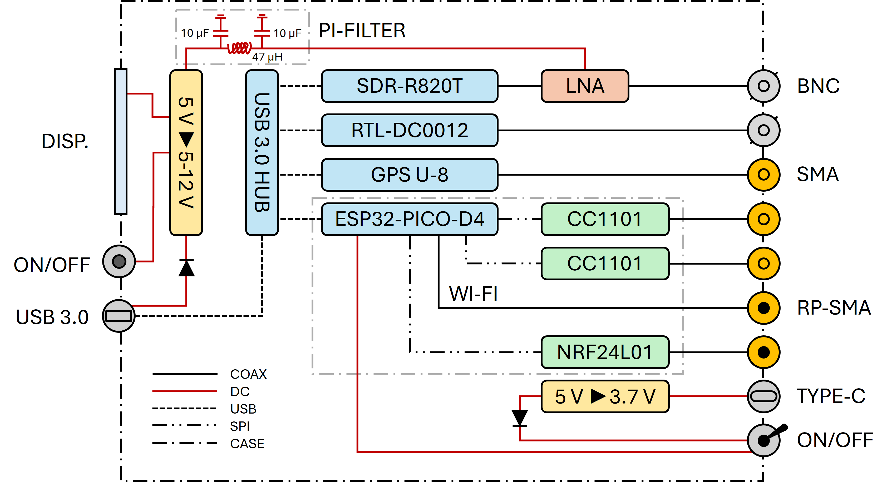
The device has two main sides: the RF panel, where all coaxial connectors are located, and the Data panel, which provides access to the device internals via USB 3.0. On the Data panel, the voltage input of the integrated LNA is displayed, adjustable via a set screw (voltage is proportional to RX amplification), and controlled by an on/off switch.
From early design stages, it was clear that all USB dongles needed to be positioned parallel to each other, aligned along their largest sides. This determined the type of USB hub required to achieve the compact form factor. A sharp but permissible bend in the hub’s extension cable was necessary to make all components fit properly within the enclosure.
The slanted surface on which the USB connector is mounted gives the unit a more versatile form factor, allowing for desktop or vertical (e.g. harness) mounting, while providing enough clearance to view and adjust the LNA settings. The enclosure was modified accordingly, and a custom aluminum panel was designed and fabricated. SolidWorks 2024 was used for the CAD phase.
3. Hardware SetupEnclosureThe enclosure used for this project originates from an AEG C-Net carryfax modem. This vintage contraption was intended for the Mercedes W126 from the 1990s as part of its communication equipment kit. Along with the matching power supply box, these units came into my possession years before the conception of this project and have since served as enclosure donors for two of my builds. Unfortunately, I never found the rest of the kit.
The aluminum extrusion that forms the enclosure gives the device a robust feel and an impression of industrial or mission-critical equipment. The second device’s enclosure (depicted last) was used for a 4 W RX/TX amplifier, which will be covered in a future report.
The main data junction for all devices and modules embedded in this unit is a USB 3.0 hub with four Type-A ports and a 20 cm extension cable. The short extension cable connects to a WY24 female-to-female watertight panel connector, which has been modified by tapping into the 5 V line of the USB connection. This line is used to power an integrated 5 V to 1.2 - 24 V variable DC converter, which subsequently powers the LNA installed between one of the onboard SDRs and its corresponding BNC port on the RF panel. The LNA provides up to 30 dB of gain, across its 100 kHz - 2 GHz operating range.
Connected to the USB hub are:
- an RTL-SDR v3 (with R820T2 chip) with the aforementioned LNA on its input,
- a second RTL-SDR DAB/DVB (with FC0012 chip),
- a U-8 GPS USB dongle (u-blox clone) with built-in LNA and bias-tee, and
- an EvilCrow RF v2 with an auxiliary 3.7 V power supply for remote operation.
To prevent reverse voltage damage to the hub or the host computer, a Schottky diode was used. On the DC-DC converter’s output side, an appropriate Pi-filter was added to reduce noise in the output voltage. The current output voltage is displayed on a 3-digit, 7-segment display on the Data panel, and the entire voltage converter can be switched on or off via a waterproof momentary switch located next to the display.
The original design used a Y-junction with dual Schottky diodes to merge the USB hub’s 5 V supply and the auxiliary Type-C 5 V supply, when both were present. This configuration was intended to provide a redundant power source for the ESP32. The auxiliary supply could take over if the USB hub’s 5 V rail could not support the total load of all connected devices. This was not the case and the original power circuit caused voltage instability on the ESP32, leading to random restarts.
To resolve the issue, a toggle switch was later added to the RF panel, allowing the auxiliary power to be turned on, only when the USB hub is unpowered. This modification explains the absence of the switch in some photos.
Embedded MicrocontrollerThe EvilCrow RF v2 is a preassembled device based on an ESP32-PICO-D4, connected via SPI to two CC1101 transceiver modules, one NRF24 transceiver module, and an SD card reader. The ESP32 can be programmed and powered via USB or alternatively can be powered by 3.7 V from its PH 2.0 port (intended for 3.7 V LiPo Battery), for remote operation. The auxiliary 3.7 V rail is down-converted from 5 V using a DC-DC buck converter. The 5 V supply originates from a USB Type-C power port on the RF panel, protected by a Schottky diode and controlled by a switch to prevent power collisions.
The board was further modified to extend the setup’s functionality. The original SMD 2.4 GHz Wi-Fi antenna was disordered, and an IPX1 (U.FL) connector was installed to allow for an externally mounted RP-SMA Wi-Fi antenna. The original onboard antenna could not operate effectively inside the thick aluminum enclosure, due to Faraday shielding. The original NRF24 module was also removed and replaced with a GT24 module (NRF24L01+PA+LNA), whose onboard PCB antenna was also switched to for another IPX1 connector for external RP-SMA antenna mounting. The new transceiver supports a range of 2.400 - 2.525 GHz in 1 MHz-increments with a transmission power of 20 dBm or 100 mW.
The microcontroller runs custom firmware that enables remote operation of the attached modules (RX/TX on the ISM bands). When powered by either supply option, the ESP32 creates a local Wi-Fi network. Connecting to it and opening the device’s local address provides a web GUI for remote RF reconnaissance and penetration tasks from a phone or laptop. Refer to the attached links for more information. I am currently developing additional software features for the EvilCrow RF v2.
RF/Data Panels and AssemblyThe RF panel of the device hosts two BNC connectors, each connected to an RTL-SDR (with the LNA placed between the R820T2 SDR and its respective connector). One SMA connector leads to the GPS module, two SMA connectors lead to each CC1101 module, and two RP-SMA connectors are used for the ESP32’s Wi-Fi and NRF24 2.4 GHz antennas, respectively. The ESP32’s auxiliary USB Type-C power port and its corresponding power switch are also mounted on this panel. All connectors are protected with water- and dustproof caps.
The custom-made Data panel was fabricated out of 1 mm aluminum sheet, cut and bent according to the initial design. The Sony screen shield was sourced from an old CyberShot camera. Within the device, coaxial cabling is kept to a minimum length and fitted with ferrite chokes to suppress common-mode currents and RF noise, while still allowing for disassembly and servicing of the unit. Any exposed circuitry or electronic components have been covered with heat-shrink tubing. Both RTL-SDRs have been fitted with aluminum heatsinks to help with heat dissipation.
The slanted corner of the original enclosure was cut using a rotary tool with a cutoff wheel and finished to fit precisely with the Data panel using metal files and progressive sanding. The original decals were left intact to preserve the vintage character of the build. The RF panel was made by drilling the required holes into one of the enclosure’s original side panels. Two mounting rails at the bottom of the unit, covered with silicone tubing, serve as support feet for stable desktop placement.
All powered components in the enclosure are interconnected using PH 2.0 connectors, allowing for quick disassembly, testing, and replacement of individual parts. Sensitive IPX coaxial cables are secured near their mounting points to prevent strain on the micro connectors. Sharp bends in the coax lines were avoided through the use of rigid adapters and careful routing.
4. Glam Shots and AfterthoughtsAll antennas, adapters, and coax cables required to cover the device’s full capabilities across its frequency range are stored in a tool roll alongside basic troubleshooting and servicing tools. The result is a compact, versatile solution. Any inconsistencies between the pictures are due to the project’s long timeline and limited documentation from my side, during assembly and troubleshooting.
During testing of subassemblies, both SDRs were evaluated for APRS, ADS-B and AIS reception, among other SDR tasks. Demodulation was handled on a Windows machine running SDR#, RTL1090 and similar tools. The presence of two VHF- and UHF-capable RTL-SDRs allowed both receivers to be used simultaneously for applications such as trunked radio communication tracking. Equivalent tests were performed with comparable software on Linux.
The LNA noticeably improved reception of faint and distant signals with minimal increase in RF noise. The GPS module acquired a valid position and PPS timing quickly. Location can be streamed as NMEA data to the local machine and overlaid with other demodulated information on a map. The EvilCrow RF operated as expected when powered via USB or the 3.7 V auxiliary supply. Adding an external Wi-Fi antenna did increase the device’s network range.
A second housing from the original W126 CarryFax kit (the power supply box) was repurposed for a related project. It now serves as the rugged enclosure for an RX/TX amplifier designed to operate alongside the device described in this report.
The amplifier, which will be covered in a separate report, provides up to 4 W transmit power in the 0.5 - 800 MHz range and up to 20 dB receive gain in the 50 MHz - 6 GHz range, powered via a 5 V USB Type-C port.
5. Links- RTL-SDR v3 (RTL2832U+R820T2) by rtl-sdr.com
- RTL-SDR DAB/DVB (RTL2832U+FC0012)
https://www.amazon.de/TenYua-RTL-SDR-RTL2832U-Receiver-Fernbedienung/dp/B08GJKRSJP
- GPS USB Dongle (M8N Chip Clone) by u-blox
- Low Noise Amplifier by GPIOLABS
- EvilCrow RF v2 (ESP32-PICO-D4 board) by joelsernamoreno
https://www.bordergate.co.uk/evilcrowrf-v2/ & https://github.com/h-RAT/EvilCrowRF_Custom_Firmware_CC1101_FlipperZero
- NRF24L01+PA+LNA (GT24)
https://www.amazon.de/-/en/dp/B09L7R7LNB
- DC-DC, Up/Down Converter with 3 Digit 7 Segment Display
https://www.amazon.de/Supply-LAOMAO-Converter-Einstellbar-Spannunswandler/dp/B0BF55Y8LQ
- DC-DC, Mini Adjustable Buck Converter
https://www.amazon.de/-/en/Converter-4-5-28V-0-8-20V-MP1584EN-Adjustable/dp/B0B92WYRR4
- USB 3.0 Hub by AXAGON
https://www.axagon.eu/en/products/hue-m1a
- WY24 USB 3.0 Connector (WY24KUSB3.0Z & WY24JUSB3.0TE) by WEIPU
https://www.weipuconnector.com/products/wy24-data/
- C-Net CarryFax Modem Enclosure by AEG
http://www.oebl.de/C-Netz/Geraete/AEG/Carryfax/Carryfax.html

Comments