The Idea behind this project is to detect fire and most importantly detection of safe to go or navigate through area for fire fighters and rescue workers with fire aftermath.
There are certain things which can be very hot but invisible to human eye and can harm the fire fighters and rescue workers. And another very important feature is air quality detection to find out if certain areas are safe for human being or not after fire.
The project consist of three main parts.
1: Drone with autonomous flight capabilities
2: Heat and air quality monitoring system
3: Real time heat and air quality mapping
Hardware Used:NXP hovergames drone is the main component of this project and is used to carry all the sensors and real time data transmission system. In case of data link lost onboard back up memory system to store all the gathered data.
Main component of this heat and air monitoring system are On Semi conductor RSL10 sense board, Sipeed longan Nano, AMG8833, MLX90614, MQ7, MQ9, nRF24L01+ with PA & LNA, separate battery and dc to dc converter. The Sipeed Longan nano is used as main control unit for gathering all the sensors information and then transmitting all these information back to ground control unit in real time. Advantage of using this board are its small size, low power consumption and onboard SD-Card storage option to store all the data. OnSemi RSL10 board is used for its very small size, ultra low power consumption and variety of onboard sensors.
Ground control setup consist of PC with QC ground control software to manage all the navigation, path planning, drone status monitoring etc. Apart from that a standalone STM32F7 discovery based real time data monitoring system is also designed. On STM32F7 board all the data gathered by drone system is received through nRF24L01+ module and then this data is overlayed in real time over the static maps collected from mapbox.com. And onboard storage capabilities is added bonus by providing an additional data backup.
One of the biggest advantage of this STM32F7 based standalone monitoring system is that multiple personal can monitor the live heat and environmental data in real time through nRF24L01+ broadcast capabilities of data transmission to multiple nodes.
The pixycam is not used in this project because at the beginning it was also malfunctioning and consuming lots of current and becoming very hot. After certain components repair it start working normally but the computation speed was very slow. Also when tested with different color/nature of fire it got confused and couldn't detect it properly so I dropped the idea of including it in final project. And replace it with AMG8833 senor because best option to detect invisible fire or hot surfaces is thermal grid sensor.
Working Principle:Originally the onboard data collection was done on NXP rapid Iot kit but in the last week it stopped working so I have to shift all the codes to another platform. And currently all the data collection is done by Sipeed longan nano board.
On Semi RSL10 board collects the light, temperature, humidity, air pressure, drone angle and then send it to Sipeed longan nano over uart. Sipeed longan nano board is connected to AMG8833 board through I2C0 (400kbps) and MLX90614 module through I2C1 (100kbps). The nRF24L01+ is connected at UART1 through ARDUINO MKRWAN1300. The MQ7 and MQ9 sensors are interfaced at PA0 and PA1 analog inputs. Onboard SD cards is connected at SPI1. FMU is connected at UART0 and it provide the GPS and other drone data. It collects all the data and transmit it through nRF24 transmitter while making a copy of same data in real time.
The FMU provide the information of current GMT and this is use to configure the GD32v103 rtc module to make time based log files.
On ground main control unit is PC with Qground control software. Along with this handheld, easily portable STM32F7 based real time data monitoring system is developed. nRF24L01+ is attached at SPI2 of STM32F746. ESP8266 module is also interfaced at UART7 for WiFi access and easy map downloading. External RAM is used for map image downloading, display frame data, map overlay data. All the data received from drone is stored on sd card along with its time. STM32F746 RTC is configured on the base of the time data received from drone.
Drone Testing and Assembly:Before starting the drone assembly everything was tested and working was verified. Unfortunately the brush-less motor quality was not good enough and one of the four motors, start producing smoke during its first run and became so hot. But later on it stopped heating up and producing any smoke but it is slightly slower then rest of the motor. Also the thread of one of the motor was damaged and its propellers was getting loose every time I change quickly decelerate the motors. And then I have to use the Loctite for firm assembly of that propeller.
All the motors wiring is solidify by adding small cable ties. Each ESC is placed on thick double sided foam tape then cable ties are used for added grip. Due to one of the propeller loosening the drone was crashed and fortunately everything remained intact except propellers. So I have added the DJI phantom3 propeller for extra protection and safety. Only Self locking nuts are used in the assembly of all the part even the circuits and propeller guards.
Software and SDK setup:For programming virtual box image provided by the hovergames team as well as mcuxpresso IDE on windows are used. Linux virtual machine is used for all the PX4 firmware development and testing.
Due to insufficient information and improper SDK of Rapid Iot Kit, I was end up installing multiple MCUXpresso IDE becuase newer version doesn't support it. All of its programming was done on v10.3.1_2233. The FMU debugger and FTDI cable was also used for its code debugging and programming (J8). During Rapid iot kit code development the biggest hardware issue was unavailability of kit 5V or 3V3 supply on mikroBUS headers. Even though the RDD-DRONE-IOT board TP38 (3V3) and TP37 (5V) has both these supplies.
First Flight:After assembly, ground testing and firmware uploading the first manual flight in stabilize mode was conducted. The result was fairly good. Due to limited space only limited distance flights was made.
Heat Sensors Interfacing:After confirming that drone can fly, it was time to interface various environmental and heat sensors with the drone. Also develop a method of quickly transfer all the gathered data to the ground control unit in real time. And at the same time should be stored onboard in case of ground control data link lost.
At the beginning MLX90614 was connected with the FMU and Thermo-Cam repository code was used to test the functionality and sensor operation. But then it was shifted to Rapid iot kit. After through testing it was found that this sensor has very limited range especially in case of a small fire so I ordered the AMG8833 sensor module for better detection of temperature hence fire. Again the range of this sensor was also found limited in case of small size fire but it was better than MLX90614. So I decided to incorporate both the sensors for better heat analysis.
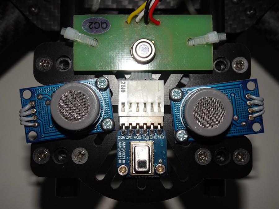
After Rapid iot kit malfunctioning the codes were shifted to Sipeed longan nano board. But to interface MLX90614 properly with this board, external pull-up resistors were added on the NXP sensor board. Also the out of the box wire was replaced with another one for easy installation with Rapid Iot kit and then Sipeed nano board.
1 / 2 • Modifications made to MLX90614 sensor board for stable Sipeed Longan Nano interfacing
Interfacing of gas sensors was rather simple and ADC interface was used to read the output reading of these sensor even though these module also provide a digital output when adjustable certain threshold of harmful gases is reached. But these digital output are not used in this project. Even though these can be used in future to get quick reading i.e: read analog value if gases threshold is not reached otherwise simply read the digital value. Adding both output will increase the number of pin count as RDD-DRONE-IOT board has very limited number of available GPIO pins.
Wireless Link Interfacing:Initial plan was to send all the sensors data to the FMU and then it will transmit all the data back to ground through MAVlink communication. But later I changed this idea and started to develop a standalone heat mapping system which can be attached to any drone. Only requirement of this system is telemetry (uart) connection with FMU for GPS and other vital data (Battery etc).
nRF24L01+ with PA and LNA was chosen because of its high data rate and log range capabilities. The addition of RSL10 ble 5.0 also enhance the possibility of long range data transmission but it is not implemented yet.
Standalone Ground Monitoring Device:Last year I developed a kids tracker using STM32F7 along with LORA module and static maps were used to display the kids location. Now in this project I have replaced the Arduino MKRWAN1300 LORA module with nRF24L01+ for high rate communication with drone. and also overlay the heat data over map frame using alpha blend (over lapping the two LCD frames with reduced alpha part). Touch GFX provide the quick way for image handling and touch capabilities. In this project touchGFX generated code is not used because with its code SD card interfacing is very difficult (almost impossible). So touch GFX is used for graphics arrangement and code generation only. Rest is loaded from SD card. PNG, 32bit BMP and JPEG images are supported.
Same code is used for this project with only change is of nRF24L01+ instead of Arduino MKRwan1300 board Lora Network. In this project still there is option to add LORA network as back but for the time being its kept for the future use only.
NXP-Hovergames mapper code is available in the repository given below. SD_DATA folder content should be placed at root directory of an SD card for correct function of the code.
High Brightness LED interfacing:High brightness led (~1W) lights are added on the drone for good visibility at night.
All the external LED lights are controlled through Arduino MKRWAN1300 board.
Also several colored LED light (both high and low brightness) are added for quick drone orientation detection at night.
This option is used on the earlier stages only.
All the onboard LED lights are controlled through external gpio exapnder IC attached with OnSemi RSL10 board.
Final DEMO:HERE
Conclusion:I faced lots of ups downs during this contest, first the drone kit was held at local customs without any logical reason and it was released in the last week of November. Then pixycam current and over heating issue. When after lots of efforts everything start working smoothly, in last week the main control board, rapid iot kit, stop working and its stop booting any more. When I tried to reprogram the firmware, the SDK directory contain nothing related to firmware as its described in NXP videos. So I have to switch to some new controller and port everything to new environment. Nevertheless The goal of fire detection and heat along with vital environmental parameter monitoring was easily implemented on Sipeed Longan Nano along with STM32F7 based mapper.
In this project, the original FMU firmware is not much altered except allowing 2nd telemetry connection and slight parameter modification and everything is kept as simple as possible and all of my focus was on my prime goal of hardware portability, easy adoption, user friendliness and most importantly it should do its job.
Future Works:The MLX90614 sensor and AMG8833 provide fairly good thermal overview of an area but have limited range. The main heat map is generated on the bases of drone angle and height. Values of FOV are taken from sensor datasheet and in future it should be verified through experiments. And also the effect of large fires on sensors readings
Also matched axis laser range finder can improve the accuracy of thermal map. Long range and high temperature range are essential to build an effective drone system.


Comments