


In a previous project, we brought up a Nios V RISC-V soft processor system on the DE10-Lite FPGA.
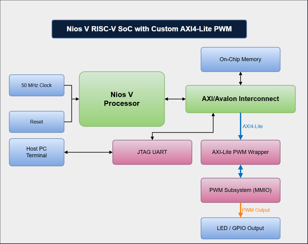
In this guide, we extend that system by adding a custom PWM peripheral and controlling it from software using memory-mapped I/O (MMIO).
This demonstrates a key concept in FPGA SoC design:
Custom hardware peripherals can be integrated into a soft-processor system and controlled directly from software.
If you don't know how to create a Nios V project or program it, please follow my previous project:
https://www.hackster.io/ederfernandotorres3/risc-v-soft-processor-system-on-de10-lite-569db8- Nios V (RISC-V) acts as the AXI master
- PWM IP is an AXI4-Lite slave
- The PWM output is exported as a conduit and routed to an FPGA pin (LED)
This project is assuming that you already finished the previous NIOS V project or that you already have the minimum files required.
In this step make sure you download the PWM files from simple repository (or the advance if you want to use the latest update) and add it to your project folder.
In your project folder create a folder named rtl, inside this folder create a folder named peripherals. It is inside this folder where you will place your pwm folder that contains the modules needed.
Add the source files into the Quartus project
Navigate to rtl > peripherals > pwm and select and open both axi_lite_pwm.sv and pwm_subsystem.sv
The files should have been added.
Once again click on the three dots, and we will add the files inside the core folder, select all three files and click open.
We will go and do this once again, but we will grab the pwm_regs.sv file inside the regs folder
We should have all this files included in our project as shown below.
Then press apply then Ok to close the window
Create the AXI4-Lite PWM ComponentFirst of all, we will need to open the niosv_system.qsys file to edit our Platform Designer system.
On the left hand panel, on the Project Navigator and select IP Components from the drop down menu.
Double-click on the niosv_system (or whatever you named it) and Platform Designer should open up with our previous Nios V system.
Double click on "New Component..."
- And Fill out the fields on the "Component Type" Tab: Name and Display Name
- Leave the "Block Symbol" tab as it is.
- For the "Files" tab, we will do something similar to what we did when we added the all the PWM rtl files in our project.
Click on Add File... and navigate to find all the PWM rtl files
You will have to select the files on each folder and click open. Do this for each folder.
Don't miss the files in the sub-folders "core" and "regs":
Once all the files are selected and opened, they should be listed on the table. There should be a total of 6 files, only 5 are visible, scroll down to make sure all the files are included.
Look for the axi_lite_pwm.sv file, and make sure that this is the Top-level File under the Attributes column. If it's not, double click on "no attributes" and make sure "Top-level File" is selected.
Click "Analyze Synthesis Files" to allow Platform Designer to infer the type protocol the Top-level File exposes. It will probably think Avalon, and this is wrong. We will have to edit manually.
- For the Parameters tab we will manual tell the Component Editor what kind of data are the parameters inside the top-level module holding.
Modify the parameter properties as follows:
AXI_ADDR_W (how many bits to represent an address): integer
AXI_DATA_W (how many bits to represent data): integer
CNT_W (how many bits to represent the period and duty): integer
APPLY_ON_PERIOD_END (do we want for new settings to only occur at the end of a PWM period): boolean
- For the Signals & Interfaces tab: in this tab we will declare the interfaces and signals required by our PWM module
As we can see, the Component Editor inferred that our top-level module has an avalon_slave interfaces, but it doesn't, the PWM module I created I wrapped it with a AXI 4 Lite Slave interface. So we will right click "avalon_slave_0" and remove it.
We should only have a clock interface with a signal named clk[1].
This clock interface and it's signal work for us, our PWM AXI interface does use a clock and we declared that signal as clk and it is 1-bit long.
For the next part, we need to make sure we name all the signals with the same name as our axi_lite_pwm.sv file (which is the top-level file).
We will start with the reset signal, on our port declaration is named: rst_n, so we need to make sure our signal is name as such.
Click on <<add interface>> and select: reset_input
For name, name it something that make sense, I will name the interface "reset".
For type, make sure to select Reset Input.
Now we have to add the signal for reset. Under the "reset" interface, there is a faint option that says <<add signal>>, click on it and select "reset".
The name for this signal needs to match the top-level file reset signal. In this case, "rst_n", so name it accordingly. It is 1-bit long as well.
Now, let's add the actual AXI 4 Lite Slave interface: Click on the faint <<add interface>> and select "AXI4Lite Slave"
You should get a windows that looks as follows:
Let's fill out the information needed:
Name (whatever you want but I recommend so the signal names can get this appened): s_axil
Type: AXI4Lite Slave
Associated Clock (whatever you named your clock interface): clock
Associated Reset (whatever you named your reset interface): reset
For associated reset, it might be glitch, but sometimes it just changes to "none" on it's own. You will get a message under "Messages"
Time to add the signals... add all the signals that it lets you choose except: arprot and awprot
As you can notice, the signal name got appended by "s_axil" at the beginning, and now their names match exactly our top-level file. Your component Editor window should look as below:
There are still some adjustments needed: We need to fix the bit-width of the signals:
s_axil_araddr: 12
s_axil_awaddr: 12
s_axil_rdata: 32
s_axil_wdata: 32
s_axil12_wstrb: 4
All the signals should look as the image below, also notice that the reset signal association for s_axil got cleared on it's own. Click on the s_axil interface and fix it if it happened to you.
So far all the signal on our port declaration have been taken care of, except: cnt, period_end, and pwm_raw.
We don't need cnt, and period_end since they can be accessed through registers and I just exposed the signals during development for debugging purposes.
But the signal: pwm_raw, it is required, it is the main reason we are doing this whole project.
So we need to add an interface for pwm_raw, since this signal will be exposed outside Platform Designer, it needs to be selected as a conduit so we can later export it.
Click on <<add interface>> one more time and select: conduit.
Use the following settings for the conduit PWM:
Name: PWM (whatever you want really)
Type: Conduit
Associated Clock: clock
Associated Reset: none
Now this interface needs a signal; select <<add signal>> and click on the "*" and we are going to reference the pwm_raw signal from axi_lite_pwm.sv file.
For this signal we are going to use the following settings:
Name: pwm_raw
Signal Type: conduit
Width: 1
Direction: output
And once again, on my computer, s_axi forgot it's associated reset, so I'll go back and fix it one more time.
Click on File > Save
and then click Finish...
This should have popped up:
Now, the PWM module should be wrapped up with everything needed to integrate it into our system using Platform Designer. It should show up now on the left panel with whatever name was used, in our case Basic AXI Lite PWM.
Double click on it, and the settings windows should open up to modify the parameter settings that are located on the top-level file.
I'll leave the settings as they are which are, 12, 32, 32 and True, in their respective base ;), then click on "Finish"
Connect the signals as follows (source > axi4_lite_pwm_basic port):
- clk > clock
- out_reset > reset
- data_manager > s_axi
and double click on the PWM's Export column, that one that says: Double-click to export
It should now be bold:
The system will probably display an error saying the memory overlaps with another component's memory region. To fix this we need to assign our PWM component a memory address that doesn't overlap anything else.
The system can find this automatically by going to System > Assign Base Addresses
Make sure to save the changes by going to File > Save
Then, click on the Generate HDL... button on the bottom-right corner and press Generate button on the window that just opened.
Instantiate the NIOSV_SOPC systemAs in the previous project, navigate into the pd folder inside our project folder. Inside this folder look for the folder with the same name as the system we created (in this case, mine is niosv_system, on the github repository for "beginners", it will be named "system"). Inside this folder, open up the verilog file named after the system. as shown below.
Copy all the code and we'll paste it on the DE10_LITE_Golden_Top.v file (we'll be replacing the old instantiation). And we'll connect the signals with the boards GPIO/buttons/clock pins:
- .clk_clk > MAX10_CLK1_50
- .reset_reset_n > KEY[0]
- axi4_lite_pwm_basic_0_pwm_conduit > LEDR[0]
As in the previous project, Start Compilation.
Once it's finished successfully. Program the FPGA development boardGo to your sw/app/main.c file that we had edited and compiled on the previous project.
Now, we have to define the peripheral Memory Mapped Addresses, in Platform Designer we can see that the base address for our pwm module is 0x0003_0000
and on the axi_lite_pwm.sv file that I have provided, you can see the Register map for each register for this module as seen below.
We need to make sure we define these value and give it an alias in our main.c file (it can later be moved to a header file, but for simplicity, we'll leave it on the main.c file for now)
Replace the code with this:
#include <stdio.h>
#include <stdint.h>
#include <unistd.h>

#define	PWM_BASE	0x00030000

#define	REG_CTRL	(*(volatile uint32_t*)(PWM_BASE + 0x00))
#define	REG_PERIOD	(*(volatile uint32_t*)(PWM_BASE + 0x04))
#define	REG_DUTY	(*(volatile	uint32_t*)(PWM_BASE + 0x08))
#define REG_APPLY	(*(volatile uint32_t*)(PWM_BASE + 0x0C))
#define REG_STATUS	(*(volatile uint32_t*)(PWM_BASE + 0x10))
#define REG_CNT		(*(volatile uint32_t*)(PWM_BASE + 0x14))

int main(void)
{
    printf("\n\nstart\n");

    printf("Write period for blinking\n");
    REG_PERIOD = 25000000;
    printf("period ok\n\n");

    printf("Write duty for blinking\n");
    REG_DUTY = 12500000;
    printf("duty ok\n\n");

	printf("Write 1 to bit 0 (enable) in CTRL\n");
	REG_CTRL = (1u << 0);
	printf("bit 0 set to 1: done!\n\n");

	printf("write: 1 to apply\n");
	REG_APPLY = 1;
	printf("REG_APPLY set to 1: done!\n\n");

	printf("sleeping for 2 seconds\n");
	usleep(2000000);
	printf("sleeping done\n\n");

	printf("status = 0x%08lx\n", REG_STATUS);
	printf("ctrl reg = %lu\n", REG_CTRL);
    printf("cnt    = %lu\n", REG_CNT);
	printf("DUTY REG = %lu\n", REG_DUTY);
	printf("PERIOD REG = %lu\n", REG_PERIOD);

	printf("\n");

	printf("Write PERIOD for smooth LED intensity\n");
    REG_PERIOD = 50000;
	REG_DUTY	= 0;
    printf("PERIOD ok\n\n");

	printf("write: 1 to apply\n");
	REG_APPLY = 1;
	printf("REG_APPLY set to 1: done!\n\n");

	printf("status = 0x%08lx\n", REG_STATUS);
	printf("ctrl reg = %lu\n", REG_CTRL);
    printf("cnt    = %lu\n", REG_CNT);
	printf("DUTY REG = %lu\n", REG_DUTY);
	printf("PERIOD REG = %lu\n\n\n", REG_PERIOD);

	while(1)
	{
		//ramp up
		for(int32_t d = 0; d <= 50000; d += 100)
		{
			REG_DUTY = d;
			REG_APPLY = 1;
			usleep(2000);
		}

		//ramp down
		for(int32_t d = 50000; d >= 100; d -= 100)
		{
			REG_DUTY = d;
			REG_APPLY = 1;
			usleep(2001);
		}
	}

	return 0;
}Visit my previous project to build the BSP, compile, and download the code to the FPGA board, the link is found here.
After programming the Nios V microcontroller and running juart-terminal, the output should look like this:
and LEDR[0] on the board should be dimming in and out.


Comments