



Hardware components | ||||||
 |
| × | 1 | |||
| × | 9 | ||||
| × | 1 | ||||
| × | 1 | ||||
| × | 1 | ||||
| × | 1 | ||||
| × | 1 | ||||
Software apps and online services | ||||||
| ||||||
| ||||||
| ||||||
| ||||||
| ||||||
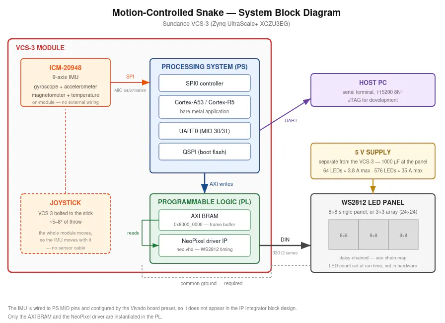
This project builds on Nathan Sweeney's FPGA Snake design. His original project was a playable Snake game on a 24×24 WS2812 LED matrix driven by custom PL logic on a Zynq UltraScale+ MPSoC. My adaptation replaces the keypad controls with a 3D-printed physical joystick; this has the VCS3 board bolted to it and controls the snake via gyroscopes on the module’s integrated IMU.
The finished unit boots from onboard flash with no computer attached, and the identical application runs on either the board's application processor or its real-time processor.
This is written as a full tutorial, describing the steps throughout Vivado, Vitis, with later stages describing the journey of debugging, troubleshooting and testing.
Notes on Wiring:WS2812 wires can be unforgiving against faulty connections. Ensure:
- 330 Ω series resistor on the LED data line, close to the first panel.
- 1000 µF capacitor across the panel supply at the panel end.
- Common ground between the VCS-3 and the panel supply.
- Flying leads are loose enough - the finished unit gets physically pulled and shaken.
Jet Joystick - Free 3D Print Model - MakerWorld
The joystick is heavily based on an already-existing model from MakerWorld (linked above), which we then modified. The original design mounted a lightweight, 3D-printed aeroplane, intended for display purposes - not a game - so most of the modifications made were to enhance the smoothness and improve the robustness of the mechanism.
A main point of weakness seemed to be the bar underneath, connecting the joystick to the moving base, with a lot of bend and twist preventing the base from moving as much as we needed. After iterating through a few different designs, a larger, square bar seemed to be the best fit. This was printed in PETG instead of PLA for added strength.
Another point of failure was the joystick itself, with the post connecting the stick and the spring often snapping. We removed the 3D-printed post entirely and replaced it with a metal 3mm thread, which proved to be much more robust. To allow for this, we also modified the connector to the bar to have a brass insert so the 3mm thread could attach to it.
Everything was made to fit exactly / be printed in place, but we experienced issues with both the joystick and the moving base printing slightly too big. The joystick is printed in place with the ball floating but attaching just enough to hold its place in the print then be broken free, but ours were not breaking free so the joystick was unable to move. Similarly, the base was printing slightly too big, causing much friction when moving and getting stuck when moved too far in any given direction. Reducing the flow rate when printing helped massively with both of these issues.
We also found that the joystick was designed to move smoothly back and forth and side to side but not front to side or side to back etc., which was not ideal as the latter are the key movement patterns for the snake game. The stronger bar and more clearance in the base by sanding down enough to remove the ridges made these movements possible and much smoother.
Other than the bar and the connectors, all other components are from the original STL files. Remember to reduce flow rate and use the same print settings for all, as they are made to fit exactly so reducing flow rate on some and not others led to issues of some parts being too big and not fitting well.
Board Holder
We needed a compact board holder stack which included the VCS3 MIPI camera/display adapter board, the VCS-3 and a fan for the VCS-3 to replace the model aeroplane from the original design. We designed a stack with the minimum possible clearance for each board and a cutout for the JTAG cable for debugging and flashing, complete with a cube on the bottom board to slot onto the moving platform. Small movements of the joystick move the board quickly and significantly enough to pick up a change in direction, which was exactly what we intended.
Finally, we designed and printed a base for all components, fitting both the joystick setup and the LED panels.
Go to the Sundance github repository:
https://github.com/SundanceMultiprocessorTechnology/VCS-3
Navigate to ‘Code’ → ‘Download ZIP’.
Then copy the ‘board_files’ to the location you plan to use for the project.
Now open Vivado.
File → Project → New, choose RTL Project and tick ‘Do not specify sources at this time’, then click Next.
Click Boards and select the VCS-3. If the board files are newly installed, you may need to click Refresh so that the board shows up as an option.
Then click Next → Finish.
The LED panels are driven by a NeoPixel (WS2812) VHDL core, so go to the github repository:
https://github.com/ATaylorCEngFIET/neo_pixel_ip
Full credit to Adam Taylor.
Click Code → Download ZIP and save to your preferred location. Unzip the file there.
Now in the sources window, click ‘+’ to add sources. Select ‘Add or create design sources’ → Next → + → Add files, and then select the file neo.vhd, and click OK.
Click Finish.
Navigate to Design Sources → neo_pixel(rtl) (neo.vhd). Find line 58 of the code, and change 1023 to 4095. Then Save File.
Now to develop the block design...
In the Flow Navigator click ‘Create Block Design’ (found beneath IP INTEGRATOR). In the window that comes up, click OK.
Right-click on ‘neo_pixel(rtl) (neo.vhd)’ and then ‘Add Module to Block Design’.
In the block diagram tab go to ‘+’ in the top toolbar to Add IP. Search for the Zynq UltraScale +MPSoC and select it.
Click ‘Run Block Automation’ at the top of the block diagram.
Make sure all options are ticked in the window which pops up. Click OK.
Double click on the Zynq block and navigate to Clock Configuration → Output Clocks → Low Power Domain Clocks → PL Fabric Clocks.
Alter settings as shown:
Click OK.
(Apart from the PL fabric clocks, nothing else in the processing system needs touching. The board preset has already configured LPDDR4, QSPI boot flash and both SPI buses, including the SPI0 bus carrying the module's onboard 9-axis IMU. That makes the VCS-3 a natural choice for motion-sensing work,with no external module, wiring and no configuration to get wrong).
Add the Block Memory Generator and AXI BRAM Controller using the ‘+’ button in the block diagram toolbar.
Double-click the Block Memory Generator and, under ‘Memory Type’, select ‘True Dual Port RAM’.
Click OK.
Double-click the AXI BRAM Controller and change Number of BRAM interfaces from 2 to 1.
This is because only BRAM port A is being controlled with AXI control, whereas port B will read and write to the neopixel IP.
Click OK.
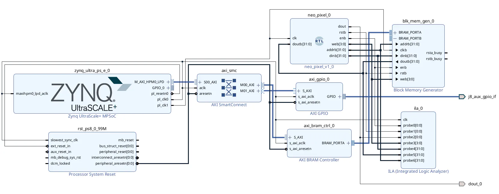
Your block design should now look like this:
Select the ‘Board’ panel in the sources window and double-click aux gpio on connector j8.
With GPIO selected, click OK. A new block, AXI GPIO, should appear in the design.
Now, add an ILA (Integrated Logic Analyzer) IP Block.
Double-click the new ILA block and, under Monitor Type, select Native. With the Number of Probes set to 7 and Sample Data Depth set to 16384. Leave all other General Options as they are, then navigate to Probe_Ports(0..6). Settings should be as follows:
Click OK and select Run Connection Automation within the green banner – in the popup window, ensure all blocks available are ticked. Click OK.
Right-click the clk port on the neo_pixel_0 and select Disconnect Pin. Then, find pl_clk1 on the Zynq block, and drag that open pin to the newly available clk pin on the neo_pixel. Then, also connect this same clk pin to clkb, under the Block Memory Generator’sBRAM_PORTB, such that the block design looks like (see the orange selected connection):
Right-click dout on the neo_pixel_0 and select Make External. Then, connect all pins under BRAM_PORTB to their corresponding pins on the neo_pixel_0 (e.g. rstb →rstb).
Then navigate to the probe pins of the ILA. Connect them as follows:
probe0[0:0] → enb
probe1[0:0] → rstb
probe2[0:0] → dout
probe3[3:0] → web[3:0]
probe4[31:0] → dinb[31:0]
probe5[31:0] → doutb[31:0]
probe6[31:0] → addrb[31:0]
As long as the probe widths match with the other port widths, it will work.
Regenerate layout in order to clean up your view of the block design.
Click ‘+’ in the sources window, select Add or create constraints → Create file → name: ‘constraints.xdc’ → Finish. Select the new constraints.xdc file and open up the editor.
Type in:
set_property PACKAGE_PIN B10 [get_ports dout_0]
set_property IOSTANDARD LVCMOS33 [get_ports dout_0]
Save the file.
Validate the design by pressing F6. Then, right-click design_1 (design_1.bd) in the sources tab and select Create HDL Wrapper, with ‘let Vivado manage wrapper and auto-update’ selected.
Finally, it is now possible to run synthesis, run implementation, and generate the bitstream. By clicking Generate Bitstream in the Flow Navigator, this is all executed automatically. Launch runs on local host and click OK. Only select a high number of jobs if your computer can handle it.
Once generated, export the hardware and bitstream by navigating to File → Export → Export Hardware (with ‘Include Bitstream’ selected). Save the ‘.xsa’ file in a convenient location.
Software Design in VitisVitis 2024.2 uses the Unified IDE.
Set Workspace to a new folder within your project folder, but a separate folder from where the Vivado project files are located.
Once loaded, Create Platform Component and name it ‘platform’, for simplicity. Under Flow, select Hardware Design and Browse for the exported ‘.xsa’ file.
Under OS and Processor, select the following settings:
Note that the A53 is a choice here, not a requirement: the VCS-3's XCZU3EG carries quad Cortex-A53 application cores and dual Cortex-R5 real-time cores. The same 'Snake' game can run unmodified on either - a platform can host both domains side by side, so you can switch processor architecture later without touching your hardware design or any application code.
Click Next → Finish.
Navigate to File → New Component → Application. Click through the options, selecting your platform, ‘platform’, and the standalone_psu_cortexa53_0. Do not add any Source Files. Click Finish.
Open app_component → Sources → src. Right-click src and click Add File. Name the file exactly as ‘numbers.h’. Repeat and add another file, naming it ‘snake.c’.
From the bottom of this Hackster page, copy and paste the provided ‘numbers.h’ and ‘snake.c’ code into Vitis. Select platform in the Vitis Explorer panel, then click Build in the Flow panel. Once this completes, select app_component in the Vitis Explorer panel, then click Build in the Flow panel.
There may appear to be red errors in the code. However, if you find this line towards the end of snake.c:
#include “xbram_hw.h”
and delete / re-type the line, the errors should disappear (this is a peculiar bug in Vitis 2024.2).
There may still be yellow warning errors, but these can be ignored.
Before progressing any further, ensure that there is a green tick next to the Build button. This verifies that your application built successfully.
Now, on your VCS-3, set the boot mode switch SW1 to OFF/OFF in order to select JTAG. See below.
Power the VCS-3 over USB and switch it on. You should see a green flashing LED on the underside of the board.
[Note: if you are running Vitis in a Virtual Machine, select Devices in the VM’s menu bar, navigate to USB and ensure Digilent USB Device is selected. Without this the host sees the device and Vitis sees nothing.]
With the app component selected, hover over Debug and click the settings wheel to open launch.json.
Bitstream file should be automatically selected (if not, locate your ‘.xsa’ file’s corresponding ‘.bit’ file). The Target Setup Mode should be Baremetal Debug, and Board Initialization should be set to FSBL, with fsbl.elf already automatically selected as the FSBL file. Then, ensure these options are ticked:
- Init With FSBL
- Reset Entire System
- Program Device
Click New next to Target Connection. Set Type to Hardware Server and Port to 3121. Tick Use Symbol Server. As for the Host, set ‘127.0.0.1’, however, if this does not work then open your Ubuntu terminal and run
/tools/Xilinx/Vivado/2024.2/bin/hw_serverThe last line of this reports the URL to connect to, for example: TCP:AMD-2024:3121
Test Connection before clicking OK. If connection fails then Vitis should instruct how the hardware server can be reached.
Check that all settings in launch.json are as follows:
Now open a serial terminal at 115200 8N1 on your system. For example, using PuTTY:
Now, click Run under app_component.
A successful run should give a serial terminal output like so:
The LED panels should also light up, giving a green snake comprising 3 LEDs, and a red apple, represented by 1 red LED.
At this stage, it should be possible to play the game. Rotate the joystick right to start. A quick, slight flick of the joystick will initiate movement because the game is built using gyroscopes; as opposed to accelerometers which rely on position, gyros are based on rate of angular rotation, which is much more fitting for a joystick setup.
Throughout play, ensure that movements with the joystick are sharp and deliberate, otherwise the IMU’s gyros may not correctly exceed value thresholds when required. Furthermore, after each game, hold the joystick in a neutral position, as there is a calibration period between runs during which the IMU must be stationary to give a reliable datum.
Once you have confirmed that everything works as expected, it is worth programming the QSPI flash so that your setup can become a self-contained unit.
With the app component selected, click Create Boot Image. In the new window, select Browse next to Output Image* and select a location to store your BOOT.bin file; within the app_component folder is fine. Click Save.
Do the same for the Output BIF File Path*. Note that it does not matter what the ‘.bif’ file name is; just click Save in the same location as for your BOOT.bin file.
Since this tutorial is for the A53 CPU, ensure that Destination CPU is set to a53-0.
Ensure that all settings match those in the images above, and click Create Image.
Assuming this was successful, navigate to Vitis → Program Flash…, and configure the settings as shown under the Program Flash Memory popup window.
The Image File should be the BOOT.bin file created previously, with the Connection as the one you have already used to successfully target the VCS-3. Once all settings are configured correctly, and without touching the physical VCS-3 switches yet, click Program.
Wait for a Flash Operation Successful message in the Output terminal.
Now, disconnect power from the board and set the VSC-3’s SW1 switch to OFF/ON (QSPI ROM).
Now you can disconnect JTAG entirely. After power-cycling the board it should be possible to play Snake on your system as an entirely self-contained unit. Congratulations!
Trusting the SensorThe build is done. From here on the project will describe analysis rather than instructions. For my adapted C code, most ofwhat changed falls into three areas: how input arrives, how fast the loop runs, and how the board boots.
Early on, with the board sitting still, the gyro reported values swinging between 2000 and 20000. The X-axis and Y-axis readings were frequently identical to one another. Identical readings mean the same bytes are being interpreted as two different axes: a misaligned burst read, or off-by-one buffer indices. That redirected the investigation towards considering that my reads were wrong.
The second trap is calibration itself. Averaging 50 samples at 10ms means a 500 ms window during which the board must be still. Held tilted or moving during it, the datum is wrong for the whole session.
Re-timing the Game LoopThe keypad version had one loop and one rate: poll, move, draw, sleep 120 ms. Sensible, because a human holds a button for hundreds of milliseconds and 120 ms is also a good snake speed.
However, a joystick flick is less definitive than a button press, so more samples are needed in order to make meaningful and accurate observations; fewer samples might miss the peak velocity of a joystick flick, meaning that thresholds are not correctly exceeded. For the first attempt we chose
TICK_MS 50which helped but caused the snake to move much faster, making the game borderline unplayable (unless you're exceptionally good at Snake!). This called for a re-design:
#define TICK_MS 5              // input poll interval, 200 Hz
#define GAME_MOVE_TICKS 24     // snake moves every 24 polls = 120 ms
read_gyro_input();                       // every 5 ms
if (alive) {
game_move_counter++;
if (game_move_counter >= GAME_MOVE_TICKS) {
game_move_counter = 0;
game_tick();                     // every 120 ms
draw_game_frame();
}
Note that 5 x 24 = 120ms. This is deliberately identical to the original game speed; only now there was the added bonus of a greater input sampling rate.
This fast poll allows several consecutive readings to occur within one “quick” jolt of the board. This was important because a “confirm counter” could be implemented, which required that a series of samples must all exceed a given threshold for a movement to be registered; without the freedom to implement this, only a single reading could be read during a board movement, opening up vulnerability to random spikes which might erroneously satisfy threshold requirements.
At 200 Hz a 150 ms flick gives thirty samples, so the confirmation count becomes a useful filter for legitimate movements to be registered. (Eventually, it turned out that ~6 samples were appropriate).
Three other sections of code were relying on TICK_MS being 120, and all three broke when it became 5.
Firstly, the idle screen redrew 24x too often.wait() contained draw_game_frame(), usleep(1000 * TICK_MS). Therefore its redraw rate was tied to the same constant. At 120 ms that was a frame push about 8 times per second, so at 5 ms it became 200 times a second. Each push is 1728 AXI writes, so the idle screen went from roughly 14, 000 writes per second to 345, 000, along with 24x the LED current (to display a snake that isn't moving). This was fixed by giving it its own constant, WAIT_DRAW_TICKS.
The turn cooldown became 24x shorter.GYRO_COOLDOWN counts loop passes, not milliseconds. The early gesture code used a value of 3, which at TICK_MS 120 was a 360 ms lockout after each turn. At TICK_MS 5 that same 3 means 15 ms, which was too short. It eventually had to become 40 to restore roughly the same 200 ms.
Debug printing started distorting the loop.xil_printf is blocking: it doesn't return until the characters have gone out of the UART. A 40-character line at 115200 baud takes about 3.5 ms, and the loop period is 5 ms. Printing gyro values on every sample therefore nearly doubles the loop time, so the game runs slower while you are measuring it. Debug prints in the sample path need throttling; print once every 100 passes, roughly twice a second.
The requirement was that any transition of the joystick should register the same way regardless of where it starts.
At ±2g the ICM-20948 gives 16384 counts per g, so tilt θ produces 16384 × sin(θ). That is roughly 1430 counts at 5°, 2280 at 8°, 3400 at 12°. The accelerometer version classified each reading into five zones with hysteresis. Some aspects of this design included: one axis is selected (comparing magnitudes, so a diagonal resolves to one direction rather than commanding both); zones are edge-triggered, executing on the transition; and neutral is a zone like any other, tracked but commanding nothing.
The joystick had 5-8° of mechanical throw. 8° is about 2280 counts; the enter threshold was 3500, roughly 12°. The joystick physically could not reach it and lowering the threshold did not help either, since at just 5° of throw the signal was continually corrupted by noise.
An accelerometer measures absolute tilt; a gyroscope measures rotation rate. Rate depends on how fast you move, not how far, so a quick flick (regardless of angle traced) produces a large reading. At ±250 dps the gyro gives 131 counts per °/s, and a brisk flick easily reaches 2000-10000. This fit the constrained-range control offered by the mechanical setup.
A gyro can not sense a held position, but this was not relevant in the end. For Snake, discrete 90° turns (not continuous steering) drive the game. The gyros perfectly accommodate for this.
Tuning by MeasurementSetting thresholds began by guessing. At GYRO_THRESH 5000 (about 38 °/s) nothing registered so this was dropped to 3000 with GYRO_CONFIRM_COUNT 30. However, it was still barely responsive.
It turned out that ‘confirm count’ was causing the difficulty. 30 samples at 5 ms demands 150 ms of continuously sustained rotation. A real flick accelerates, peaks and decelerates; it might exceed threshold for 60 ms, drop below while your hand slows, and never achieve thirty in a row. Dropping to GYRO_CONFIRM_COUNT 6 changed the feel significantly.
Finally, we measured raw readings over UART while performing a sequence; pause, up, slowly back to neutral, and so on through all four directions. Afterwards we analysed the log.
It turned out that the axes have completely different noise floors. X wobbles by ±1000 while “stationary”. Also visible were occasional corrupt reads, values like X=32906 where it was known that a signed 16-bit value cannot exceed 32767.
In the end, the settings were as follows: GYRO_THRESHOLD 1800, set by the worst axis rather than the average, with GYRO_CONFIRM_COUNT 6 and GYRO_COOLDOWN 40.
As mentioned, on the VCS-3 it is possible to run using the R5 CPU or the A53 CPU. The A53 features 64-bit, far more compute, and it runs from DDR so code size barely matters. The R5, however, is better when timing has to be dependable, it can run entirely from its 64 KB tightly-coupled memories with single-cycle access and no DDR latency or cache misses, so a control loop takes the same time every iteration. For Snake either is fine so the choice is free, and on a board with both you can put a hard real-time loop on the R5 while the A53 handles everything else.
To enable the R5, add a psu_cortexr5_0 domain to the existing platform, create an app component on it, copy the sources, tick Enable RPU Split Mode, and set the flash partition to destination_cpu = r5-0.
Note that under JTAG an A53 app runs fine with Board Initialization = TCL or FSBL, but the R5 needs FSBL, which performs RPU power and reset handling which psu_init.tcl doesn't cover.
Adding More RandomnessPlayers noticed that the apple kept appearing in the same places, particularly in the first few games after switching the board on. The game had become predictable.
The cause was the line intended to seed the random number generator:
rng_state ^= (u32)BramBase ^ 0x9E3779B9u; // "random seed"BramBase is the BRAM's base address, fixed at compile time. 0x9E3779B9 is a literal constant. XORing two constants together produces a third constant, so rng_state held exactly the same value every time the board started. The generator is deterministic, so an identical starting value produces an identical sequence of food positions; the same first apple, the same second apple, and so on, on every single power-up.
The fix was to seed the generator from something that genuinely varies between power-ups. Two sources were readily available: gyroscope noise (using the low bits) and human reaction time (the idle screen polls at 200 Hz while waiting for the player to flick the joystick, giving thousands of different starting points).
One further change improves the spread of positions. xorshift32 produces its weakest, most patterned bits in the low end of the word, and % WIDTH uses precisely those. Shifting right by 16 first
(xor_shift32() >> 16) % WIDTH
takes the stronger upper bits instead, which removes the faint diagonal banding that was visible in where food appeared.
Why the VCS-3 Suited This ProjectThe IMU is on the module, so mounting the board ensures that the sensor is correctly aligned and wired, with no cable or separate supply. Furthermore, there were two processor architectures on one part, running the same application with no source changes and one bitstream. The board files do the tedious part, configuring QSPI, SPI, I2C, UART, GPIO, timers, USB and LPDDR4 from a single preset.
Thanks again to Adam Taylor whose github provided the LED driver.


Comments