

Hardware components | ||||||
| × | 1 | ||||
 |
| × | 1 | |||
Software apps and online services | ||||||
 |
| |||||
 |
| |||||
 |
| |||||
| ||||||
If you have played with the PIC-IoT WG Development Board, you might be familiar with connecting the board to a Wi-Fi access point, establishing a connection to the cloud and visualizing the real-time graphs of the on-board light and temperature sensor data on the PIC-IoT webpage. If you haven't, please read the AVR-IoT WG and PIC-IoT WG Quick Start Guide.
In addition to publishing its own data, the PIC-IoT development board is capable of subscribing to a topic, after which it can receive data from the Google Cloud whenever data to that topic is published to the broker server.
Subscribing to topics is desired when the receiver is interested in the information sent to the broker by other connected client devices publishing data using the subscribed topic. For example, firmware OTA (Over the Air) updates can be handled using the publish/subscribe model. After sending a 'SUBSCRIBE' packet, all the messages published on the specific topic of subscription are received by the board and as of today, all PIC-IoT boards subscribe to the ‘/devices/{deviceID}/config’ topic by default.
What you will learnIn today's article, I will cover the following:
- Use the “Control your device” section present on the www.pic-iot.com webpage to send data down to a PIC-IoT board and view the data using a serial terminal.
- Add an OLED C click board to the board via MCC and view the published data on the OLED click.
Follow the Quick Start Guide to connect the board to Wi-Fi and run the demo.
This tutorial will use MPLAB X and MPLAB Code Configurator (MCC).
Follow the Development Requirements for PIC-IoT WG and AVR-IoT WG Tutorial for instructions on how to install the MPLAB X and MCC development environment.
Setup your development environment and get started on building a sensor node foundation. We will build off of this pre-configuration to customize the design.
Visualizing the published data via a serial termAfter a successful connection to the Google Cloud, you should have arrived at the following screen in which the temperature and light sensor graphs are plotted.
Scroll a little further and you should find the 'Control Your Device' section. Here you will find 3 specific functions created by us for demo purposes.
- Toggle Button: The toggle switch value corresponds to a short forced ON/OFF state to the yellow LED on the PIC-IoT board. The LED will stay ON/OFF for a short time depending on the position of the toggle switch. After which, the LED will resume normal blinking behavior to indicate the transmission sensor data through 'PUBLISH' packets
- Text Field: The message typed in the text field is transmitted in the form of a string to the board
- Sliders: Slider position will be sent to the board
You can also add additional buttons by clicking the 'Add' button or change the names for these buttons using the edit feature next to button title.
Before hitting the "Send to device" button, connect a serial terminal application like Tera Term, PuTTy, cool term etc with the following settings
Hit the "Send to Device" button and see the data on your serial terminal
This data should match the button settings on the PIC-IOT.com webpage you set earlier.
Note that there is no permanent storage, or collection of the data published by the boards connected through the Microchip sandbox account. The full storage features available by the Google Cloud are available to the user after the board has been removed from the demo environment (Microchip Sandbox) and migrated to a private account.
Visualizing the subscribed data on an OLED C click board™Before you start, make sure you have the following software versions taken care of:
- MPLAB® X IDE v5.20
- MPLAB XC16 compiler v1.36b
- MPLAB Code Configurator v3.75 or later
- Foundation Services Library v0.1.34
- MCHP-IOT Library v2.00 (PIC-IOT v1.1.1)
- MikroElektronika Click Library v1.1.1
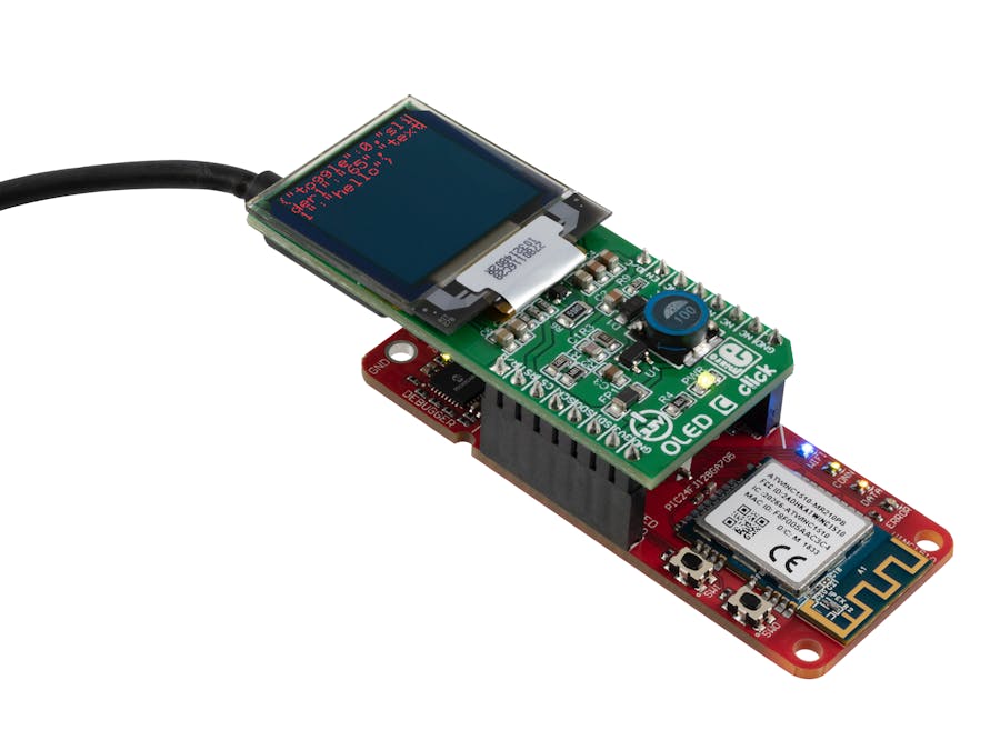
Now go ahead and plug the OLED C click on to the PIC-IOT Board as shown below.
1. Connect the board to your PC and follow the steps described in the sensor node foundation tutorial to create a new project in MPLAB X. This process is crucial in adding the basic PIC-IOT WG Sensor Node to your project.
2. Open MCC if you have closed it.
3. To add the OLED C click library to your project, navigate to Device Resources (bottom left) and scroll to the list to expand the Mikro E-Clicks folder.
4. Select oledC under Display and double-click to add it to the project.
*Note: Make sure you have added the PIC-IoT WG sensor node indicated in step 1 before adding the oledC to your project.
5. Upon adding the oledC, you should see a screen shown below. I have highlighted the 'notifications window' indicating that we need to assign pin connections to the OLED C click we just added.
6. Before we get to the pin manager, navigate to advanced settings and change the SPI for the oledC to SPI2 (it defaults to SPI1, which is used by the WINC controller).
7. Navigate to the pin manager and configure pin functions using the table below as reference:
Pin manager with the above configuration (highlighted blocks should match table above).
8. Navigate to the Notifications tab to verify all pins have been assigned with no warnings (ignore TMR2).
9.Click the Generate button in the Resource Management window (top left) to add the generated header files to your project.
Successful generation complete:
10. Now that we have completed the MCC portion of the setup, let's navigate back to your project files and open our main.c file under Source Files.
11. Add the following oledC include files.
#include "mcc_generated_files/oledC.h"
#include "mcc_generated_files/oledC_shapes.h"
12. To further assist you, we have created the following helper function that helps in displaying the data received from the cloud on to the oledC click in an optimized format. Add this section of code right after the include section described in step 11.
static void oledC_displayDataFromCloud(uint8_t *payloadString);
static void oledC_displayDataFromCloud(uint8_t *payloadString)
{
   uint8_t x;
   uint8_t y;
   uint8_t screen[16];
   uint8_t *toscreen;
   toscreen = payloadString;
   oledC_setColumnAddressBounds(0,96);
   oledC_setRowAddressBounds(0,96);
//    toscreen = strstr((char*)payload, textToken);
   for(x = 0; x < 96; x++)
   {
       for(y = 0; y < 96; y++)
       {
           oledC_sendColorInt(0x0);
       }
   }
   y=0;
   while((*toscreen!=NULL)&&(y<6))
   {
       if(strlen(toscreen) >= 16)
       {
           strncpy(&screen[0], toscreen, 16);
           oledC_DrawString(0, y*8, 1, 1 , &screen[0], 0xf800);
           for(x=0;x<16;x++)
           {
               toscreen++;
           }
       }
       else
       {
           strcpy(&screen[0], toscreen);
           oledC_DrawString(0, y*8, 1, 1 , &screen[0], 0xf800);
           while(*toscreen!=NULL){
               toscreen++;
           }
       }
       y++;
   }
}
13. To call this oledC display function we just created, simply insert the following call function statement from within the 'receivedFromCloud' function.
oledC_displayDataFromCloud(payload);
Here is a screenshot:
14. Clean and Build the project by pressing the hammer icon in the toolbar
15. Make and Program the board using the green arrow button on the toolbar.
15. Navigate back to the CURIOSITY drive.
16. Open CLICK-ME.htm to open the uniquely configured Google Cloud portal.
17. Scroll to the Control Your Device section and set your values for each of the functions ( Toggle, Text Field and Sliders) and when ready, hit the 'Send to device' button to see the data now being displayed on the OLED C click.
18: Subscribed data visualized on your OLED C click.
That's it for today's demo! Share your thoughts and questions in the comments section below!


Comments