


Hardware components | ||||||
 |
| × | 1 | |||
 |
| × | 1 | |||
Software apps and online services | ||||||
 |
| |||||
 |
| |||||
Follow this tutorial and build a foundation for deeper sensor node design through adding configuration for the WINC1500 Wi-Fi network controller, ATECC608A secure element, and other components on your board. From there, you will be in a good position to start customizing and innovating your unique application.
Before you startFollow the Quick Start Guide to connect the board to Wi-Fi and run the demo.
This tutorial will use MPLAB X and MPLAB Code Configurator (MCC).
Follow the Development Requirements for PIC-IoT WG and AVR-IoT WG Tutorial for instructions on how to install the MPLAB X and MCC development environment.
Note that AVR-IoT WG can also be programmed using the START/ Studio environment.
1. Plug the board into your PC and open MPLAB XYou can verify that the PIC-IoT WG (or AVR-IOT WG) board is detected by checking for the presence of its “Kit Window”
Click the icon to open the new project Wizard.
Choose Microchip Embedded and Standalone and hit Next
Chooseyour device:
For PIC-IoT WG, the device is PIC24FJ128GA705
For AVR-IoT WG, the device is ATmega4808
The next screen will instruct you to select the programmer and debugger tool. MPLAB X will recognize the serial number off the debugger.
Next, you will choose the compiler toolchain
For PIC-IoT WG, choose XC16 v1.36 or later
For AVR-IoT WG, choose AVR v5.4.0 or later
Assign a unique project name and save to complete the process.
3. Generate Example Files from MCCOpen MCC by clicking on the shield icon.
Confirm the default name for the MCC configuration file (MyConfig.mc3)
In the Device Resources window (bottom left of the screen), scroll to the bottom of the list and expand the Internet of Things/Examples folder
Double click to open the PIC-IoT WG Sensor Node (or AVR-IOT WG Sensor Node) module.
This will open a number of dialog windows, eventually presenting the main project configuration tab “AVR-IoT WG Sensor node” or "PIC-IoT WG Sensor node"
NOTE: the loading and configuration process can be quite lengthy. Depending on your PC performance, allow for several seconds for the above window to open and populate. Several tabs will be added to the editor window. You will want to close most of them (i.e. select the last tab and right click to select “Close Other”)
You do not need to modify anything with MCC for this tutorial, but keep it in mind as it will be a useful tool when you dive deeper into your application. Hit Generate to add the generated files to your project.
4. Make and Program your ProjectInspect the Project window and expand the Source Files/MCC Generated Files tree
IMPORTANT: After the project is generated, MPLAB X proceeds to scan the source files (in a background task) to retrieve information that will be useful in assisting the editing and debugging process later (i.e. auto-completion, cross-referencing…) but also automatic makefile generation! You MUST wait until the process is completed (see progress bar at the bottom of the screen) before you continue to the next step!
Click the hammer and brush icon in the toolbar to Clean and Build (compile) the entire application for the first time.
When the build is successful, program the device by clicking on the Make and Program icon in the toolbar
When the programming sequence is complete observe the device startup led sequence and watch it reconnect to the last configured Wi-Fi Access Point and eventually to the Google Cloud.
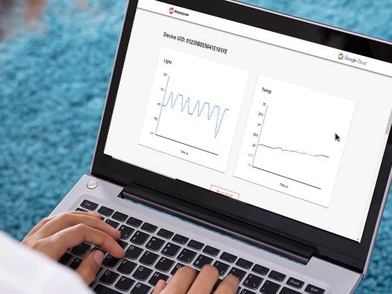
Verify that data from the basic sensor set is being transmitted successfully to the Google cloud by accessing the device unique landing page (clicking on the CLICK-ME.HTM file or scanning the QR code under the board)
You have now learned how to program your AVR-IoT WG or PIC-IoT WG development board from the MPLAB X environment. You can now further develop your sensor end node by plugging a MikroElektronika Click board into the mikroBUS socket and configuring it in MCC.
TroubleshootingIf you encounter compilation errors, make sure your software development environment is up to date. Follow the Development Requirements for PIC-IoT WG and AVR-IoT WG Tutorial to learn more.


Comments