

One of the great advantages of FPGAs is there true parallel nature, this makes them ideal for applications like RADAR, Communications, Radio, Broadcast, Medical Imaging, Quantum Computing and of course Electronic Warfare.
For these applications the FPGA is always connected with a high speed, wide band ADC and DAC often operating at Giga Samples per seconds.
the RFSoC from AMD, first introduced in 2019 addresses this challenge with the introduction of several Giga Sample Per Second ADCs and DACs on the same silicon as the programmable logic.
How many ADCs and DACs and supported sampling frequency depends on the generation of the RFSoC.
- GEN1 6.554 GSPS DACs, 4.096 GSPS ADCs
- GEN2 6.554 GSPS DACs, 2.220 GSPS ADCs
- GEN3 9.85 GSPS DAC, 5 GSPS ADCs
- DFE 9.85 GSPS DAC, 5.9 GSPS ADCs
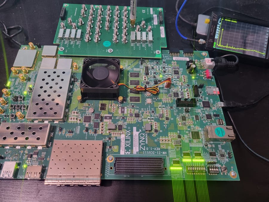
In this project we will be looking at the ZCU111 development board which is a contains a RFSoC GEN1.
ArchitectureThe RFSoC is a heterogeneous SoC, which contains the processing system the same as for the MPSoC, with the exception of the Mali GPU.
While the programmable logic is based on the UltraScale+ fabric and contains DSP48s, Block and UltraRAM and transceivers in common with most MPSoC devices.
Where it differs however is the RFSoC contains RF Data Convertors within the programmable logic which contain several GSPS ADC and DACs.
The RF ADCs and DACs interface with the user logic via AXI Streams the widths and data rates of these links depends upon the configuration of the RF Data convertors.
Within the RF DAC there are several elements which enable us to generate useful RF signals
- Support for real or I/Q Outputs
- FIFO Gear Box to accommodate AXI Stream Interface
- I/Q RF Mixer
- Interpolation
- RF DAC
- RF Clock distribution
While the RF ADC provides users
- Support for real or I/Q Inputs
- RF ADC
- FIFO Gear Box to accommodate AXI Stream Interface
- I/Q RF Mixer
- Decimation
- RF Clock Distribution
Internally the RFADC and RFDAC are arranged in tiles, each tile contains several ADCs and DACs. The number of ADCs and DACs depends upon the specific generation, and device however, there will be either two or four in a tile. Each tile has its own RF reference clock on dedicated package pins.
Typically these dedicated RF clocks are connected to a RF clock generator / PLL to enable dynamic reference frequency selection.
Lets take a look at how we can generate a simple tone with an RFSoC.
Hardware DesignFor this project we will be using the ZCU111 as the target reference board. We will be using the XM500 RF break out board which provides SMA access to the ADC and DAC outputs.
To get started we need to open Vivado 2025.2 and create a new project which targets the ZCU111 board.
Give the project a name and location.
Select RTL project and we will provide the source later.
Search for the ZCU111 on the boards tab.
Click Finish to create the project.
Click on create block diagram.
On the diagram add in a Zynq UltraScale+ MPSoC Processing System.
Run the block automation to configure the PS for the ZCU111.
Add in a RF Data Convertor.
Run the block automation on the RF Data Convertor.
Connect the reference clocks to the dedicated RF Reference Clocks.
The diagram should look similar to below.
Re Customise the RF Data Convertor,
Enable DAC one on Tile 229 and set it for a real output, 8x interpolation and 1 sample per clock. Leave the mixer bypassed.
On the clocking tab select a sampling rate of 2.456 GSPS with a reference clock of 122.8 MHz.
This will give an output design as shown below, make the DAC reference clock external. Add in a DDS Compiler and set it for the output frequency you desire.
Lets talk about the clocking we have a sampling rate of 2.456 GSPS this is provided by a RF refence clock which is 122.8 Mhz. The sample rate is 20 times the RF reference clock.
We have also set the interpolation to be 8x, what this means is 0 zeros are inserted between sample provided to the DAC. This does not move the frequency of the input signal. However it prevents a lot of aliasing in the spectrum, as the original data was sampled at 307 MHz (307 MHz x 8 = 2.459 GHz).
If we want to put the generated signal higher in spectrum we need to use the mixer. This also means that our usable bandwidth is (307 / 2) MHz or 153.5 MHz.
Of course we can get much better performance than this using lower decimation, the mixer to move the signal in the frequency spectrum.
Software DevelopmentThere is not much to do for the SW development however we can use it to ensure the status of the PLLs and the RF DAC.
The RF Path is simple so we it will start running once the device is programmed and the RF Clocks are present.
#include "xil_printf.h"
#include "xil_io.h"
#include "sleep.h"
#include "xil_cache.h"
#include "xrfdc.h"
#include <metal/sys.h>
#include <metal/io.h>
#define RFDC_BASEADDR      (0xB0000000U)
#define RFDC_REGION_SIZE   (0x40000U)
#define DAC_TILE_ID        1
#define DAC_BLOCK_ID       0
/* Units are MHz */
#define DAC_REFCLK_MHZ     (250.0)     /* e.g. 250.0, 245.76, etc */
#define DAC_FS_MHZ         (2500.0)    /* e.g. 2500.0 for 2.5 GSPS */
/* =========================================================== */
static inline u32 Peek32(u32 a) { return Xil_In32(a); }
static int MetalInitCompat(void)
{
#ifdef METAL_INIT_DEFAULTS
struct metal_init_params mip = METAL_INIT_DEFAULTS;
return metal_init(&mip);
#else
return metal_init(NULL);
#endif
}
static void MetalIoInitCompat(struct metal_io_region *io,
void *virt,
metal_phys_addr_t *physmap,
size_t size)
{
metal_io_init(io,
virt,
physmap,
size,
(unsigned int)(-1),
0,
NULL);
}
static const char* MixerTypeStr(u32 t)
{
switch (t) {
case XRFDC_MIXER_TYPE_OFF:     return "OFF";
case XRFDC_MIXER_TYPE_COARSE:  return "COARSE";
case XRFDC_MIXER_TYPE_FINE:    return "FINE";
case XRFDC_MIXER_TYPE_DISABLED:return "DISABLED";
default: return "UNKNOWN";
}
}
static const char* MixerModeStr(u32 m)
{
switch (m) {
case XRFDC_MIXER_MODE_OFF: return "OFF";
case XRFDC_MIXER_MODE_C2C: return "C2C";
case XRFDC_MIXER_MODE_C2R: return "C2R";
case XRFDC_MIXER_MODE_R2C: return "R2C";
case XRFDC_MIXER_MODE_R2R: return "R2R";
default: return "UNKNOWN";
}
}
static void DumpIPStatus(XRFdc *p)
{
XRFdc_IPStatus ip;
u32 st = XRFdc_GetIPStatus(p, &ip);
xil_printf("GetIPStatus st=%lu\r\n", (unsigned long)st);
if (st != XRFDC_SUCCESS) return;
xil_printf("IP state=%lu\r\n", (unsigned long)ip.State);
for (int t = 0; t < 4; t++) {
xil_printf("DAC tile %d: enabled=%lu tileState=%lu powerUp=%lu pllState=%lu blocksMask=0x%02x\r\n",
t,
(unsigned long)ip.DACTileStatus[t].IsEnabled,
(unsigned long)ip.DACTileStatus[t].TileState,
(unsigned long)ip.DACTileStatus[t].PowerUpState,
(unsigned long)ip.DACTileStatus[t].PLLState,
(unsigned)ip.DACTileStatus[t].BlockStatusMask);
}
}
static void DumpPll(XRFdc *p, u32 tile)
{
u32 clkSrc = 0, pll = 0;
u32 st1 = XRFdc_GetClockSource(p, XRFDC_DAC_TILE, tile, &clkSrc);
u32 st2 = XRFdc_GetPLLLockStatus(p, XRFDC_DAC_TILE, tile, &pll);
xil_printf("ClockSource st=%lu val=%lu\r\n",
(unsigned long)st1, (unsigned long)clkSrc);
xil_printf("PLLLock   st=%lu val=%lu (%s)\r\n",
(unsigned long)st2, (unsigned long)pll,
(pll == XRFDC_PLL_LOCKED) ? "LOCKED" : "UNLOCKED");
XRFdc_PLL_Settings ps;
u32 st3 = XRFdc_GetPLLConfig(p, XRFDC_DAC_TILE, tile, &ps);
xil_printf("GetPLLConfig st=%lu\r\n", (unsigned long)st3);
if (st3 == XRFDC_SUCCESS) {
u32 ref_mMHz = (u32)(ps.RefClkFreq * 1000.0);
u32 fs_mMHz  = (u32)(ps.SampleRate * 1000.0);
xil_printf("  Enabled=%lu Ref=%lu mMHz Fs=%lu mMHz RefDiv=%lu FbDiv=%lu OutDiv=%lu\r\n",
(unsigned long)ps.Enabled,
(unsigned long)ref_mMHz,
(unsigned long)fs_mMHz,
(unsigned long)ps.RefClkDivider,
(unsigned long)ps.FeedbackDivider,
(unsigned long)ps.OutputDivider);
if (ps.OutputDivider != 0) {
u32 calc_mMHz = (ref_mMHz * ps.FeedbackDivider) / ps.OutputDivider;
xil_printf("  Calc Fs=%lu mMHz\r\n", (unsigned long)calc_mMHz);
}
}
}
/* NEW: apply ref/fs and verify lock */
static int EnsureDacPllLocked(XRFdc *p, u32 tile, double ref_mhz, double fs_mhz)
{
u32 pll = 0;
u32 st  = XRFdc_GetPLLLockStatus(p, XRFDC_DAC_TILE, tile, &pll);
xil_printf("EnsurePllLocked: pre st=%lu pll=%lu\r\n",
(unsigned long)st, (unsigned long)pll);
if (st != XRFDC_SUCCESS) return XRFDC_FAILURE;
if (pll == XRFDC_PLL_LOCKED) return XRFDC_SUCCESS;
xil_printf("PLL not locked -> DynamicPLLConfig(ref=%.6f MHz, fs=%.6f MHz)\r\n",
ref_mhz, fs_mhz);
/* NOTE: in 2025.2 the clock source macro is XRFDC_INTERNAL_PLL_CLK */
st = XRFdc_DynamicPLLConfig(p, XRFDC_DAC_TILE, tile,
XRFDC_INTERNAL_PLL_CLK,
ref_mhz, fs_mhz);
xil_printf("DynamicPLLConfig returned %lu\r\n", (unsigned long)st);
if (st != XRFDC_SUCCESS) return XRFDC_FAILURE;
usleep(300000); /* give PLL time */
st = XRFdc_GetPLLLockStatus(p, XRFDC_DAC_TILE, tile, &pll);
xil_printf("EnsurePllLocked: post st=%lu pll=%lu (%s)\r\n",
(unsigned long)st, (unsigned long)pll,
(pll == XRFDC_PLL_LOCKED) ? "LOCKED" : "UNLOCKED");
return (pll == XRFDC_PLL_LOCKED) ? XRFDC_SUCCESS : XRFDC_FAILURE;
}
static void DumpDacBlockStatus(XRFdc *p, u32 tile, u32 block)
{
XRFdc_BlockStatus bs;
u32 st = XRFdc_GetBlockStatus(p, XRFDC_DAC_TILE, tile, block, &bs);
xil_printf("GetBlockStatus(DAC t%lu b%lu) st=%lu\r\n",
(unsigned long)tile, (unsigned long)block, (unsigned long)st);
if (st != XRFDC_SUCCESS) return;
u32 fs_mMHz = (u32)(bs.SamplingFreq * 1000.0);
xil_printf("  Fs=%lu mMHz Analog=%lu Digital=%lu ClksOk=%u FIFOflagsEn=%u FIFOflagsAsrt=%u\r\n",
(unsigned long)fs_mMHz,
(unsigned long)bs.AnalogDataPathStatus,
(unsigned long)bs.DigitalDataPathStatus,
(unsigned)bs.DataPathClocksStatus,
(unsigned)bs.IsFIFOFlagsEnabled,
(unsigned)bs.IsFIFOFlagsAsserted);
}
static void DumpDacStaticSettings(XRFdc *p, XRFdc_Config *CfgPtr, u32 tile, u32 block)
{
xil_printf("---- DAC static settings (from driver/config) ----\r\n");
u32 interp = 0;
u32 st_i = XRFdc_GetInterpolationFactor(p, tile, block, &interp);
xil_printf("InterpolationFactor st=%lu val=%lu\r\n", (unsigned long)st_i, (unsigned long)interp);
u32 fabWords = 0;
u32 st_f = XRFdc_GetFabWrVldWords(p, XRFDC_DAC_TILE, tile, block, &fabWords);
xil_printf("FabWrVldWords st=%lu val=%lu (words/cycle)\r\n", (unsigned long)st_f, (unsigned long)fabWords);
u32 nz = 0;
u32 st_nz = XRFdc_GetNyquistZone(p, XRFDC_DAC_TILE, tile, block, &nz);
xil_printf("NyquistZone st=%lu val=%lu\r\n", (unsigned long)st_nz, (unsigned long)nz);
XRFdc_Mixer_Settings ms;
u32 st_m = XRFdc_GetMixerSettings(p, XRFDC_DAC_TILE, tile, block, &ms);
xil_printf("MixerSettings st=%lu\r\n", (unsigned long)st_m);
if (st_m == XRFDC_SUCCESS) {
xil_printf("  Type=%s Mode=%s CoarseFreq=0x%lx Freq=%.3fMHz Phase=%.2f Scale=%u\r\n",
MixerTypeStr(ms.MixerType),
MixerModeStr(ms.MixerMode),
(unsigned long)ms.CoarseMixFreq,
ms.Freq,
ms.PhaseOffset,
(unsigned)ms.FineMixerScale);
}
if (CfgPtr) {
u32 fe = CfgPtr->DACTile_Config[tile].DACBlock_Digital_Config[block].FifoEnable;
u32 dw = CfgPtr->DACTile_Config[tile].DACBlock_Digital_Config[block].DataWidth;
u32 dt = CfgPtr->DACTile_Config[tile].DACBlock_Digital_Config[block].MixerInputDataType;
xil_printf("Cfg: FifoEnable=%lu DataWidth=%lu MixerInputDataType=%lu\r\n",
(unsigned long)fe, (unsigned long)dw, (unsigned long)dt);
}
}
static void ForceDisableAllADCs(XRFdc_Config *CfgPtr)
{
for (int t = 0; t < 4; t++) {
CfgPtr->ADCTile_Config[t].Enable = 0;
CfgPtr->ADCTile_Config[t].PLLEnable = 0;
CfgPtr->ADCTile_Config[t].NumSlices = 0;
CfgPtr->ADCTile_Config[t].SamplingRate = 0.0;
CfgPtr->ADCTile_Config[t].RefClkFreq = 0.0;
CfgPtr->ADCTile_Config[t].FabClkFreq = 0.0;
for (int b = 0; b < 4; b++) {
CfgPtr->ADCTile_Config[t].ADCBlock_Analog_Config[b].BlockAvailable = 0;
CfgPtr->ADCTile_Config[t].ADCBlock_Digital_Config[b].DataWidth = 0;
CfgPtr->ADCTile_Config[t].ADCBlock_Digital_Config[b].DecimationMode = 0;
CfgPtr->ADCTile_Config[t].ADCBlock_Digital_Config[b].FifoEnable = 0;
CfgPtr->ADCTile_Config[t].ADCBlock_Digital_Config[b].MixerType = XRFDC_MIXER_TYPE_OFF;
CfgPtr->ADCTile_Config[t].ADCBlock_Digital_Config[b].NCOFreq = 0.0;
}
}
xil_printf("Forced all ADC tiles disabled in CfgPtr\r\n");
}
int main(void)
{
XRFdc RFdcInst;
XRFdc_Config *CfgPtr;
int mst;
u32 Status;
xil_printf("\r\n--- RFDC DAC bring-up / full dump ---\r\n");
Xil_DCacheDisable();
Xil_ICacheDisable();
xil_printf("Caches disabled\r\n");
CfgPtr = XRFdc_LookupConfig((metal_phys_addr_t)RFDC_BASEADDR);
if (!CfgPtr) {
xil_printf("ERROR: XRFdc_LookupConfig(0x%08lx) returned NULL\r\n",
(unsigned long)RFDC_BASEADDR);
while (1) {}
}
ForceDisableAllADCs(CfgPtr);
xil_printf("Preflight peek @Base+0x000 = 0x%08lx\r\n", (unsigned long)Peek32(RFDC_BASEADDR + 0x000));
xil_printf("Preflight peek @Base+0x004 = 0x%08lx\r\n", (unsigned long)Peek32(RFDC_BASEADDR + 0x004));
mst = MetalInitCompat();
xil_printf("metal_init = %d\r\n", mst);
if (mst != 0) {
xil_printf("ERROR: metal_init failed\r\n");
while (1) {}
}
static struct metal_io_region rfdc_io;
metal_phys_addr_t pa = (metal_phys_addr_t)RFDC_BASEADDR;
void *va = (void *)(uintptr_t)RFDC_BASEADDR;
MetalIoInitCompat(&rfdc_io, va, &pa, RFDC_REGION_SIZE);
for (unsigned i = 0; i < sizeof(RFdcInst); i++)
((volatile u8 *)&RFdcInst)[i] = 0;
RFdcInst.BaseAddr = (metal_phys_addr_t)RFDC_BASEADDR;
RFdcInst.io       = &rfdc_io;
RFdcInst.device   = NULL;
xil_printf("Calling XRFdc_CfgInitialize...\r\n");
Status = XRFdc_CfgInitialize(&RFdcInst, CfgPtr);
xil_printf("CfgInitialize = %lu\r\n", (unsigned long)Status);
if (Status != XRFDC_SUCCESS) {
xil_printf("ERROR: CfgInitialize failed\r\n");
while (1) {}
}
xil_printf("\r\n[POST INIT]\r\n");
DumpIPStatus(&RFdcInst);
DumpPll(&RFdcInst, DAC_TILE_ID);
/* NEW: only thing you needed to change for new clocking */
Status = EnsureDacPllLocked(&RFdcInst, DAC_TILE_ID, DAC_REFCLK_MHZ, DAC_FS_MHZ);
xil_printf("EnsurePllLocked = %lu\r\n", (unsigned long)Status);
DumpDacBlockStatus(&RFdcInst, DAC_TILE_ID, DAC_BLOCK_ID);
DumpDacStaticSettings(&RFdcInst, CfgPtr, DAC_TILE_ID, DAC_BLOCK_ID);
xil_printf("\r\nStarting DAC tile %d...\r\n", DAC_TILE_ID);
Status = XRFdc_StartUp(&RFdcInst, XRFDC_DAC_TILE, DAC_TILE_ID);
xil_printf("StartUp(tile %d) = %lu\r\n", DAC_TILE_ID, (unsigned long)Status);
xil_printf("\r\n[POST STARTUP]\r\n");
DumpIPStatus(&RFdcInst);
DumpPll(&RFdcInst, DAC_TILE_ID);
DumpDacBlockStatus(&RFdcInst, DAC_TILE_ID, DAC_BLOCK_ID);
DumpDacStaticSettings(&RFdcInst, CfgPtr, DAC_TILE_ID, DAC_BLOCK_ID);
xil_printf("\r\nDone.\r\n");
while (1) { usleep(1000000); }
}To test this application, we need a spectrum analyser, in this case I will be using a Tiny SA Ultra.
I have connected this to the SMA for DAC 229 Channel 0 as on the XM500 breakout boards these are connected to a Balun to create a signal ended signal.
Before we can see the output tone however we need to first program the RF Clocks using the ZCU111 Board User Interface.
This provides clock configuration files for the RF Clock Generators at 122.8 MHz.
Successful programming will report back the programmed frequency.
Prior to these being programmed you will see the RF Clock Status leds on the ZU111 board turned off.
After programming they should be turned on and illuminated.
We should then be able to see the tone as generated by the DDS on the Tiny SA, in this case at about 75MHz
This has been a simple introduction to the RFSoC and how we are able to generate tones using the DAC. We will come back in another project soon and look at the capabilities of the ADC and some more advanced features.


Comments