



Hardware components | ||||||
 |
| × | 1 | |||
Software apps and online services | ||||||
| ||||||
This project implements QR code detection and decoding on the PSOC™ Edge using a USB camera. It captures images from the camera, detects QR codes and decodes their contents so that an application can use the resulting data—for example, to trigger a command or action.
The QR code detection module continuously scans the camera feed. When it detects a QR code, it makes the decoded content available to the connected system.
To show this idea in action, the Sensor Robot for Radar Surface Detection serves as a demonstration target. The robot can already be controlled with a BLE Remote Controller, a touch display and Voice Control. Now additionally, when a corresponding QR code is detected by the front camera the vehicle will execute the encoded command.
Of course, QR code scanning might be more useful for other applications you have in mind.
The QR code detection system at a glanceThe system follows a simple processing path: a USB camera supplies images to the PSOC™ Edge application, which detects QR codes and decodes their contents. The decoded result can then be used by the application or passed to an external system to trigger an action.
Figure 1 shows the main components of the QR code detection system and how they are connected. The architecture is identical for all PSOC™ Edge E84 kits; the diagram shows the AI Kit variant used in the demonstration. The camera sends image data to the PSOC™ Edge over USB. The PSOC™ Edge processes the images and communicates with an external embedded system over an available interface, such as GPIO, UART, I²C, SPI or a CAN bus. In this project, the external system is the sensor robot, connected over CAN FD.
A touch display provides a live view from the camera, displays QR code detection results and offers controls for the scanning application. This gives the user a way to monitor and interact with the system while it is running.
HardwareThe QR code detection application uses the following hardware:
- PSOC™ Edge E84 Evaluation Kit (KIT-PSE84-EVAL): Runs the application and coordinates its tasks, including receiving camera images, detecting and decoding QR codes, and rendering the results on the display. The kit already includes a touch display and a camera module, so no additional hardware is required to rebuild this project.
- PSOC™ Edge E84AIEvaluation Kit(KIT-PSE84-AI): A more compact alternative, used for the demonstration on the Sensor Robot (see Integration with the Sensor Robot). Since the AI Kit does not include a display, the 4.3-inch touch display is connected as a separate module. The included USB camera module is connected over USB.
- USB camera(included with both kits): Supplies the images that the application scans for QR codes.
- Touch display(included with KIT-PSE84-EVAL): Shows the live camera image and detection results, and provides controls for configuring the scanning application.
The table below summarizes the differences between the two kits:
The application processes camera images in a continuous loop. The processing flow is:
- The camera captures image frames. It continuously provides new images to the PSOC™ Edge.
- The latest frame is displayed. The application updates the live camera view on the touch display.
- The scanninglibrary searches the frame. QR code detection software examines the image for recognizable codes.
- A detected code is decoded. The application extracts the text encoded in the QR code and determines its position in the image.
- The result is presented and made available. The display shows the detection result, and the application logic can use the decoded data—for example, to trigger an action in a connected system.
Several software libraries work together to handle this process:
- EmUSB provides the USB connection to the camera, allowing the application to receive image data.
- The VGLite-based image pipeline handles the camera frames and supports their processing and presentation.
- LVGL is the graphics library used to render the user interface elements — the live camera view frame, the detection overlays and the scanning controls — on the touch display.
- ZBar / Quirc perform the code detection and decoding. ZBar also supports barcodes; Quirc supports QR codes only.
The application runs on FreeRTOS and divides the QR code detection pipeline across several tasks. Figure 2 shows how camera frames and scan results flow between them.
- USBH_ISRTask manages the USB connection to the camera and captures incoming frames. It is the starting point of the pipeline: without a steady supply of camera frames, no scanning could take place.
- cm55_gfx_task receives the latest frame and updates the live camera view on the display. It also forwards the current frame to the scanning task, so the same image that the user sees is the image being analyzed.
- cm55_scanning_task processes the frame with the open-source library ZBar or Quirc. When it finds a QR code or barcode, it delivers the decoded text together with the position of the detected code in the image. The position allows the user interface to highlight the code on the display.
You can choose either library by using#defineSCAN_USING_QUIRCor#defineSCAN_USING_ZBARinscanning_task.c
- execution_task receives the decoded results and initiates the configured actions—for example, sending a corresponding command to the connected system.
This separation keeps the application reliable and responsive. Each task focuses on a single job, so continuous image capture, smooth display updates, scanning, and result handling do not interfere with each other.
Human Machine Interface (HMI)To operate and observe the QR code detection application, a 4.3-inch touch display was added to the AI Kit for this demonstration; the Evaluation Kit already includes one. It shows what the camera sees, reports detection results and lets the user configure the scanning behavior. This makes the application easy to use and understand without needing any additional tools.
As you can see in Figure 3, the display is divided into two areas: the live camera view with detection results and the scanning controls.
Camera view with detection results
Camera view: Shows the latest image from the camera, so users can see exactly what the scanning task is analyzing at any moment.
Detection results: Displays information about recognized codes. Detected codes are highlighted directly in the camera view at their position in the image.
Frame rate: Shown in the top-left corner, it indicates the camera update rate in frames per second, giving users immediate feedback on whether the system is running smoothly.
Scanning controls
Pause: Freezes the currently displayed image and detection result. This is useful for taking a closer look at a frame or a detection result.
Scanning mode: The green mode button switches between three modes:
- OFF: Disables scanning entirely. The camera view remains active, but no QR codes are detected.
- Continuous: Keeps scanning active at all times, so every code that appears in the camera view is detected immediately.
- One-Shot: Performs a single scan when requested with the capture button.
Capture: Requests a scan while in One-Shot mode.
This structure gives users full control over the detection process: they can watch the camera feed, verify detections visually and choose whether the system scans continuously or only on demand.
Integration with the Sensor Robot using CAN FDFor the integration on the Sensor Robot, the PSOC™ Edge E84 AI Kit (KIT-PSE84-AI) is used instead of the Evaluation Kit: its smaller form factor makes it easier to mount on the vehicle. Since the AI Kit does not include a display or a camera, the 4.3-inch touch display and the USB camera are connected as separate modules.
To integrate the QR code Detection with the Sensor Robot, CAN FD is used because the bus is already used within the vehicle. Figure 4 shows the QR code detection hardware integrated with the Sensor Robot.
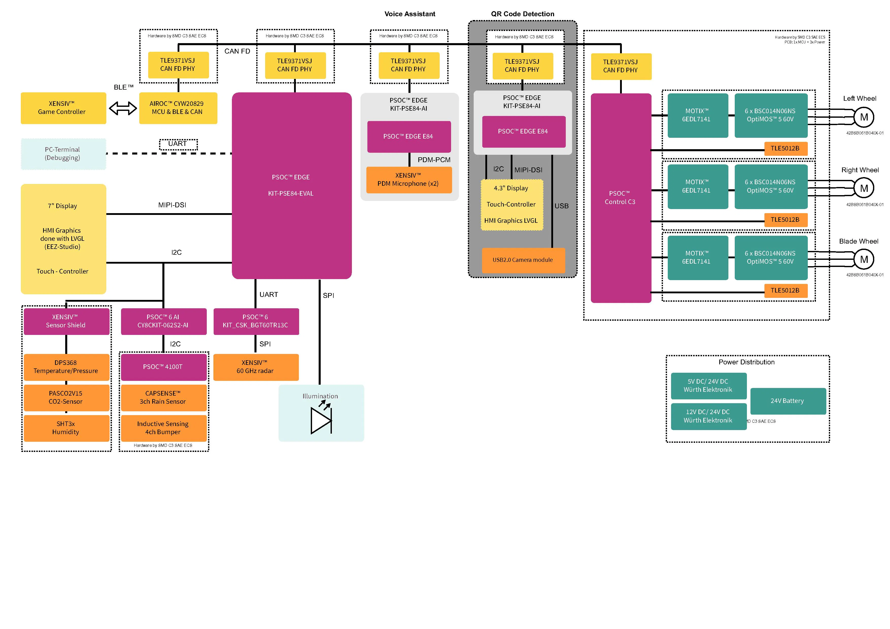
The Sensor Robot’s block diagram is shown next in Figure 5. It highlights what has been added to integrate the QR code Detection application:
- The PSOC™ Edge E84 AI Evaluation Kit is connected to both a 4.3-inch touch display and a USB Camera Module
- Additionally, the PSOC™ Edge E84 AI Evaluation Kit does not provide PHY for the CAN interface, so a CAN FD Shield is required, in this project the CAN FD Shield TLE9371VSJ is used.
The PSOC™ Edge E84 AI Evaluation Kit runs the QR code Detection application. The decoded QR code contents are mapped to commands and sent as CAN FD messages using a dedicated CAN ID. The CAN ID and message format are shared with the Voice Control implementation; see the Voice Control article.
Supported QRcode commands
(QR code text in quotation marks, followed by the robot's action.)
- Movement"Turn Left": The robot turns 90° to the left"Turn Right": The robot turns 90° to the right"Drive Forward": The robot starts moving forward"Drive Backwards": The robot starts moving backward"Stop": The robot stops all movement
- Blade"Blade Stop": The robot stops the Blade"Blade Start": The robot starts turning the Blade
- LEDs"Set LED Off": The robot turns the LEDs off"Set LED Red": The robot sets the LEDs to Red"Set LED Green": The robot sets the LEDs to Green"Set LED Blue": The robot sets the LEDs to Blue"Set LED Yellow": The robot sets the LEDs to Yellow"Set LED Pink": The robot sets the LEDs to Pink"Set LED White": The robot sets the LEDs to White"Set LED On": The robot sets the LEDs to On
- Display Tabs"Set Display Tab System": The robot opens the System Tab in the UI"Set Display Tab Control": The robot opens the Control Tab in the UI"Set Display Tab Sensors": The robot opens the Sensors Tab in the UI"Set Display Tab Capsense": The robot opens the Capsense Tab in the UI"Set Display Tab Radar": The robot opens the Radar Tab in the UI"Set Display Tab Bumpers": The robot opens the Bumpers Tab in the UI"Set Display Tab Lights": The robot opens the Lights Tab in the UI"Set Display Tab About": The robot opens the About Tab in the UI
- Other"Play Sound": The robot plays a sound
The video "QR code Detection - Result" shows the final result. The demonstration video uses the AI Kit because of its compact size; the application itself runs identically on both kits. The PSOC™ Edge E84 AI Evaluation Kit detects QR codes, maps their contents to commands and sends them via CAN FD to the Sensor Robot, which executes them.
When you watch the video, note the two views:
- Main view: The camera watches the room as the robot moves and responds to the scanned QR codes.
- HMI overlay (upper-left corner): The display shows the camera image seen by the detection application and indicates the QR codes it recognizes.
All referenced files and tasks are included in the code example under /proj_cm55/sourceThe execution_task turns a detected QR code into an action. That action could be a command sent to the sensor robot over CAN FD, or another response implemented in the application. This chapter explains how a scan result reaches the execution logic and how to add a new QR code command.
How the execution task processes scan results
The scanning task places its results in execution_scan_result_queue. Each result is stored in a scan_result_t structure. This structure contains the decoded text and information about the code’s position in the camera image. The position is useful for displaying or highlighting the code; the execution task uses the decoded text to identify the command.
typedef struct {
    int pos_x;        /* -1 indicates that no code was found in the image */
    int pos_y;
    int pts_x[4];     /* X positions of the four code corners */
    int pts_y[4];     /* Y positions of the four code corners */
    char data[256];   /* decoded text */
} scan_result_t;
The execution_task periodically checks the execution_scan_result_queue for results. Its main processing flow is:
- Receive a scan result from the queue.
- Make sure the decoded text is a valid, null-terminated string.
- Ignore results that do not contain a detected code.
- Match the decoded text against the application’s known QR code phrases.
- Ignore unknown phrases and repeated commands.
- Pass a newly recognized command to
execute_qr_command().
The code below shows the relevant structure of the task. It is shortened slightly for readability; use the project source as the reference for the complete implementation.
void execution_task(void *arg)
{
    (void)arg;

    /* Allow the robot time to finish setting up. */
    vTaskDelay(pdMS_TO_TICKS(5000));

    int32_t last_accepted_command = -1;
    scan_result_t scan;
    TickType_t last_wake = xTaskGetTickCount();

    for (;;) {
        while (xQueueReceive(execution_scan_result_queue, &scan, 0) == pdTRUE) {
            scan.data[sizeof(scan.data) - 1U] = '\0';

            if (!scan_detected(&scan)) {
                continue;
            }

            const int32_t command = get_phrase_index(scan.data);

            if (command < 0 || command == last_accepted_command) {
                continue;
            }

            last_accepted_command = command;
            execute_qr_command(command);
        }

        vTaskDelayUntil(&last_wake, pdMS_TO_TICKS(CONTROL_PERIOD_MS));
    }
}
The initial delay gives the robot time to complete its setup before it receives commands. After that, the task checks for queued results at regular intervals. The xQueueReceive() call uses a timeout of zero, so it does not wait for a result; the task processes any results already in the queue, then waits until its next scheduled check.
Writing '\0' to the last element of scan.data guarantees a null-terminated string, even if the decoded text fills the entire buffer — in that case, the final character is truncated. This allows the decoded data to be passed safely to string functions such as strcmp(). Note that with char data[256], up to 255 characters of decoded content are supported.
The last_accepted_command variable prevents the same recognized command from being executed repeatedly while the same code continues to be detected. An unknown phrase is rejected because get_phrase_index() returns a negative value when it finds no match.
Matching decoded text to a command
The get_phrase_index() function compares the decoded text with the entries in the qr_phrases array:
static int32_t get_phrase_index(const char *phrase)
{
    for (size_t i = 0; i < qr_phrases_size; ++i) {
        if (strcmp(phrase, qr_phrases[i]) == 0) {
            return (int32_t)i;
        }
    }

    return -1;
}
A match returns the phrase’s index in the array. If none of the entries match exactly, the function returns -1, which the execution task treats as an unknown command.
In this application, the scanning software can detect both QR codes and barcodes. To distinguish QR code results, the scanning task adds the prefix "QR-Code: " to the decoded text of each QR code. Therefore, the phrase stored in qr_phrases must include this prefix. For example, if the QR code contains PLAY_SOUND, the corresponding phrase might be stored as:
"QR-Code: PLAY_SOUND"The exact text must match what the scanning task provides, including capitalization, spaces and punctuation. If the strings differ, strcmp() will not find a match.
Add a new QRcode command
To connect a new QR code to an action, follow these steps.
- Choose the QRcode text and intended action
Decide what text the QR code will encode and what should happen when the application recognizes it. Keep the encoded text distinct from other commands so it is easy to identify and test.
- Add the recognized phrase
Find the qr_phrases array, where the application stores the text it recognizes. Add the new phrase using the format expected by the scanning software. For a QR code, include the "QR-Code: " prefix:
static const char *qr_phrases[] = {
    "QR-Code: PLAY_SOUND",
    "QR-Code: BLADE_STOP",
    "QR-Code: MY_NEW_COMMAND",
};
The example illustrates the format; retain the project’s existing declarations and entries when editing the actual array.
- Add a corresponding command identifier
The index returned by get_phrase_index() identifies the matched phrase. The command identifiers in the commands enum must correspond to the positions of the phrases in qr_phrases. Keep the two lists in the same order.
For example, if MY_NEW_COMMAND is the third phrase, its enum value must correspond to index 2:
enum commands {
    PLAY_SOUND = 0,
    BLADE_STOP,
    MY_NEW_COMMAND
};
Use the project’s existing enum names and order. When adding or reordering phrases, check the enum as well; otherwise, a recognized phrase could be mapped to the wrong action.
- Add the action to the execution logic
The execute_qr_command() function uses a switch statement to map a command identifier to an action. Add a case for the new identifier:
static void execute_qr_command(int32_t command)
{
    switch (command) {
        case PLAY_SOUND:
            /* Existing action */
            break;

        case BLADE_STOP:
            /* Existing action */
            break;

        case MY_NEW_COMMAND:
            /* Add the application-specific action here. */
            break;

        default:
            app_log_print("Unknown command\r\n");
            break;
    }
}
The break at the end of each case prevents execution from continuing into the next case.
The QR code detection application is designed to be extended easily. Because commands are defined in the qr_phrases array, the commands enum and the execute_qr_command() function, new QR codes can be added without changing the detection pipeline itself.
Possible extensions include:
- More QRcode values and actions: Additional QR codes can be added to trigger different commands, as described in the Tutorial. Each new code only requires a new phrase, a matching command identifier and a corresponding entry in the execution logic.
- Using the code’s position as input: The scan result already contains the position of the detected code in the camera image. This information could be used as an additional input—for example, interpreting the code’s movement in the camera view as a controller input, or reacting differently depending on where the code appears in the image.
- Connecting other systems: The decoded result does not have to control the demonstration robot. The same detection output could be passed to other systems over different interfaces, making the module usable in a wide range of applications that react to scanned QR codes.
With these possibilities, the project serves as a foundation that can be adapted to new use cases simply by defining what a scanned code should do.
SummaryThis project demonstrates QR code detection and decoding on the PSOC™ Edge E84, using a USB camera and the open available libraries Quirc or ZBar. The application processes camera images, decodes recognized QR codes and makes their contents available to trigger actions.
The Sensor Robot for Radar Surface Detection serves as one example of how decoded results can be used: QR code commands are sent to the robot, which responds accordingly. The application can also be extended by mapping additional QR code values to new commands or other application-specific actions.
What is your idea or application for QR-code or barcode scanning?


Comments