


Hardware components | ||||||
| × | 1 | ||||
Software apps and online services | ||||||
 |
| |||||
| ||||||
The goal of this project is to add offline voice control to any electronic setup so that it can react to clear spoken commands, in a way that doesn't depend on an internet connection.
At a high level, it works as a voice module that listens, recognizes commands and sends them to any system you want to control.
The device listens to a wake word (similar to saying "Alexa" or "Hey Google") and then commands (for example "drive forward", "turn left", or "set LED color green").
Because everything is processed directly on the device (no audio is sent anywhere) you get faster responses, keep your voice data local for better privacy, and the system keeps working even if there's no network.
To show this idea in action, I used the existing Sensor Robot for Radar Surface Detection as an example. The robot can already be controlled with a remote controller and a touch display, but voice makes it easier and more natural to use. You don't need to navigate menus or pick up the remote, which is especially helpful when you're busy or moving around. After saying the wake word and a command, the robot reacts: it can move forward, backward, turn, change LED colors, or play sound.
The same approach can be applied to any project where you want to control a device by talking to it.
Voice ControlThe voice interface is built using DEEPCRAFT™ Voice Assistant, an online platform that lets you create, test and deploy AI-powered voice models without needing machine learning expertise. You work in a web browser, and the tool takes care of the model design and optimization for you. Here is the system block diagram of the solution.
Note:The block diagram shows two microphones as input. In the coming example I use only one microphone.
I have followed the Getting started section on the DEEPCRAFT™ Voice Assistant user guide, which provides a detailed step-by-step tutorial. The general idea is the following:
Create the model
First go to the DEEPCRAFT™ Voice Assistant Web UI, login and create a new project by clicking on the button "Design New Project". Give it a project name and select the language.
Then add a custom Wakeword element, I have used "Hey robot".
Next, add a Text element with one or multiple phrases that describe what you want the device to do (for example, "turn on light", "light on"). Here I have added "set LED" and "turn LED".
Optionally you can add a Variable element to specify a parameter to use with the phrase. I have added a variable named "color" and entered "red", "green" and "blue" as a list.
Last, add an Intent element (I called this one "set_led_color") and connect them.
Repeat these steps to add more commands. This is how my final model looks like.
Configure the model
Once you have defined your wake word and all your commands, you can change some settings before generating the model. These are explained in the DEEPCRAFT™ Voice Assistant user guide.
I have left the default configuration and proceeded to the next step.
Generate the model
To generate the model, click on the button Generate and confirm to start the process. Depending on the complexity, it may take up to 15 minutes.
Test the model in the cloud
You can test the model in the cloud using the TestAudio Model button.
Test the model in an embedded application
Download the ready-to-integrate package (zip file) from the cloud, which contains the model and the necessary integration files.
In ModusToolbox™, create a new application using the PSOC™ Edge MCU: DEEPCRAFT™ Voice Assistant deployment template as a starting point.
Notes: See Using the code example for instructions on creating a project, opening it in various supported IDEs, and performing tasks, such as building, programming, and debugging the application within the respective IDEs.This code example supports only the Arm® and LLVM compilers, which need to be installed separately. See the Software Setup section in the example.
Drop the downloaded files into the project as shown in the following figure (this is also described in detail in the example's documentation).
Notice that the folder va_models already has some example models. To select which model gets executed, you need to open the file common.mk on the top-level application directory. Change the variable value DEEPCRAFT_PROJECT_NAME for the name of your model. In my example, it is called sensor_robot, as shown in the following figure.
Build the project and program the PSOC™ Edge E84 AI Evaluation Kit.
Use a terminal program to connect to the board. Select the KitProg3 COM port and set the parameters to 8N1 and 115200 baud.
Speak the wake word and one of the commands (for example, "Hey robot, turn left"). Confirm that the command is printed on the terminal.
Note:The Audio and Voice middleware included in the example has a limited operation of about 15 minutes with Audio Enhancement enabled, and 30 minutes with Audio Enhancement disabled. For the unlimited license, contact Infineon support.Integration with any project
We now have the PSOC™ Edge E84 AI Evaluation Kit running the voice assistant application. To integrate it with any embedded system, we can easily hack the provided example.
On the main.c file, look for the function run_voice_assistant_process. This function is called when some audio has been picked up. The audio gets processed, the voice assistant model is executed, and the results are available in the enum va_event and struct va_data.
Based on the value of va_event you can identify if a wakeword or a command have been identified.
typedef enum
{
    VA_NO_EVENT = 0,
    VA_EVENT_WW_DETECTED = 1,
    VA_EVENT_WW_NOT_DETECTED = 2,
    VA_EVENT_CMD_DETECTED = 3,
    VA_EVENT_CMD_TIMEOUT = 4,
    VA_EVENT_CMD_SILENCE_TIMEOUT = 5,
} va_event_t;
Then you can get which intent was identified, and (if applicable) its variable's value stored in the struct va_data.
typedef struct
{
    int     intent_index;
    int     num_var;
    mtb_nlu_variable_t variable[VA_NLU_MAX_NUM_VARIABLES];
} va_data_t;
The identified intent is given as an integer intent_index. The list of intents is part of the model generated files and can be found in ..\va_models\<your_model>\app_<your_model>.h
With the model I generated called "sensor_robot", the file path is ..\va_models\sensor_robot\app_sensor_robot.h
Now you can, for example, pack the information and send it via UART, I2C, CAN, etc. to your embedded system.
Integration with Arduino® using UARTFirst let's configure a UART interface on the PSOC™ Edge E84 AI Evaluation Kit.
1. On ModusToolbox™, open the Device Configurator.
2. Go to the tab "Peripherals".
3. Enable the "Serial Communication Block (SCB) 10", let's name it "VA_UART" (Voice Assistant UART) and set the personality to "UART-3.0".
4. Make sure to have the same values as shown in the picture:
- Under "General", set "Baud Rate (bps)" to 115200 and "Oversample" to 10.
- Under "Connections", set "Clock" to "16 bit Divider 1 clk", set "RX" to pin "P16[0]" and "TX" to pin "P16[1]".
5. Save and close.
Back to the main.c file in ModusToolbox™, let's add the code to initialize the VA_UART. Add these symbols and global variables:
/* Voice Assistant UART related parameters */
#define TX_BUFFER_SIZE    (4U)      // Number of bytes per UART message
#define SOP               (0xA5)    // UART Start of protocol

/* Voice Assistant UART related global variables */
mtb_hal_uart_t	            va_uart_obj;        // Voice Assistant UART object
cy_stc_scb_uart_context_t   va_uart_context;	// Voice Assistant UART context
In the main function, add the initialization code for the UART.
/* Initialize voice assistant uart */
result = (cy_rslt_t)Cy_SCB_UART_Init(VA_UART_HW, &VA_UART_config, &va_uart_context);
Cy_SCB_UART_Enable(VA_UART_HW);
result = mtb_hal_uart_setup(&va_uart_obj, &VA_UART_hal_config, &va_uart_context, NULL);
Next, add a new function called transmit_voice_assistant_command before the run_voice_assistant_process function, as shown in the following figure.
/*******************************************************************************
* Function Name: transmit_voice_assistant_command
*******************************************************************************
* Summary:
* Transfers the detected command via UART.
*
* Parameters:
*  result: result of the voice-assistant operation
*  event: state of the voice-assistant operation
*  va_data: data detected from the voice-assistant operation
*
* Return:
*  void
*
*******************************************************************************/
static void transmit_voice_assistant_command(cy_rslt_t result, va_event_t event, va_data_t *va_data)
{
    // Transmit command identified
    if (VA_RSLT_SUCCESS == result && VA_EVENT_CMD_DETECTED == event) {

        // Prepare message with intent and variable values
        uint8_t intent = va_data->intent_index;
        uint8_t value = va_data->variable[0].value;
        uint8_t crc = SOP ^ intent ^ value;
        uint8_t tx_msg[TX_BUFFER_SIZE] = {SOP, intent, value, crc};
        size_t tx_length = TX_BUFFER_SIZE;

        // Send message to control LED
        mtb_hal_uart_write(&va_uart_obj, tx_msg, &tx_length);
    }
    return;
}
This function will pack the voice assistant command into a 4-byte message:
- SOP: Start of protocol (0xA5).
- Intent: The index that represents the intent associated with the recognized command.
- Value: The variable value, if applicable (for example, for the intent
set_led, the variable we defined is the LED color). - CRC: A checksum to confirm the integrity of the message.
You can find the list of intents and variable values in the file va_models/sensor_robot/app_sensor_robot.h.
The figure highlights the intent and values we need for the Arduino® example.
Now, let's add the call to the function transmit_voice_assistant_command from within run_voice_assistant_process.
/* Transmit command identified */
transmit_voice_assistant_command(va_result, va_event, &va_data);
Compile and flash the code with these changes. When a voice command is recognized, a 4-byte UART message is sent.
Now to the Arduino® IDE, where the UART message will be processed to turn ON or OFF the built-in LED. The Arduino® listens on the UART at 115200 baud and processes incoming bytes using a simple state machine. I am using an Arduino® UNO board for this example.
// UART protocol: [ 'A5', intent, variable, crc ]
// crc = 'A5' XOR intent XOR variable
const uint8_t LED_PIN = LED_BUILTIN;
const uint32_t BAUD = 115200;
const uint8_t SOP = 0xA5; // Start of protocol
const uint8_t LED_CONTROL_INTENT = 0x03; // "intent" value matching voice assistant
enum RxState { WAIT_START, READ_INTENT, READ_VAR, READ_CRC };
RxState state = WAIT_START;
uint8_t intent = 0, var = 0, crc = 0;
void setup() {
pinMode(LED_PIN, OUTPUT);
digitalWrite(LED_PIN, LOW);
Serial.begin(BAUD);
}
void handleByte(uint8_t byte) {
switch (state) {
case WAIT_START:
if (byte == SOP) state = READ_INTENT;
break;
case READ_INTENT:
intent = byte;
state = READ_VAR;
break;
case READ_VAR:
var = byte;
state = READ_CRC;
break;
case READ_CRC: {
crc = byte;
uint8_t calc = SOP ^ intent ^ var;
if (crc == calc) {
if (intent == LED_CONTROL_INTENT) {
digitalWrite(LED_PIN, (var != 0) ? HIGH : LOW);
}
}
// resync for next frame (even if CRC fails)
state = WAIT_START;
} break;
}
}
void loop() {
while (Serial.available() > 0) {
handleByte((uint8_t)Serial.read());
}
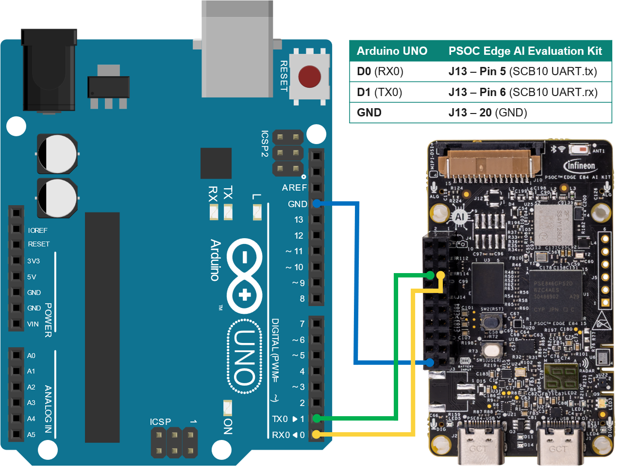
}Finally, flash the code to the Arduino® and connect both boards as shown in the following figure.
Note:
PSOC™ Edge ports 16 and 17 use 3.3 V logic. Arduino® uses 5 V logic
Safe: PSOC TX → Arduino RX
Not safe: Arduino TX →PSOC RX (voltage divider or level shifter required)
Try it out. Control the built-in LED on the Arduino® by speaking the commands "Hey robot, set LED on" and "Hey robot, set LED off".
Integration with the Sensor Robot using CAN FDTo integrate the voice control with the Sensor Robot, I have used CAN FD because this bus is already used within the vehicle. Here are a couple of pictures showing the PSOC™ Edge E84 AI Evaluation Kit mounted on the Sensor Robot and the HMI showing the voice assistant output.
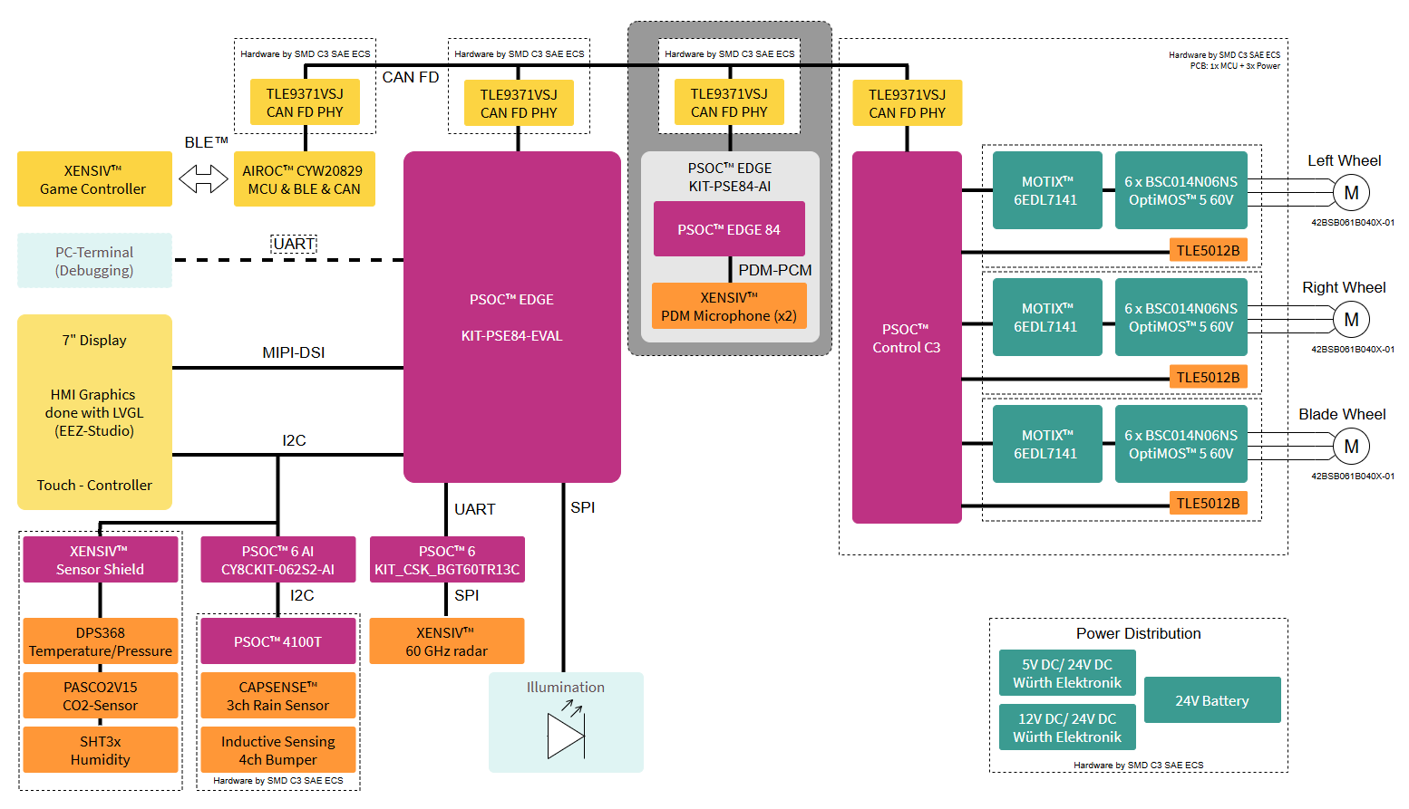
The Sensor Robot's block diagram is shown next. It highlights what has been added to integrate the Voice Assistant application:
- The PSOC™ Edge E84 AI Evaluation Kit which comes with on-board XENSIV™ MEMS digital microphones.
- Additionally the PSOC™ Edge E84 AI Evaluation Kit does not provide a PHY for the CAN interface, therefore a CAN FD Shield is required (I have used this one: CAN FD Shield TLE9371VSJ).
Note:Please refer to the Sensor Robot for Radar Surface Detection project for further details on the rest of the components shown in the block diagram.
The following picture shows the PSOC™ Edge E84 AI Evaluation Kit and highlights the on-board XENSIV™ MEMS digital microphones. The one highlighted in blue is used in this project.
Note:The PSOC™ Edge E84 AI Evaluation Kit provides two CAN channels. Both are available on the J14 connector Expansion IO Header.- CAN channel 0 Rx: P16_0, Tx: P16_1 (Used in this project)- CAN channel 1 Rx: P16_2, Tx: P16_3Unfortunately, you cannot use the OV7675 camera that comes with the kit at the same time as the CAN bus with this board, as it shares the same J14 connector.
The PSOC™ Edge E84 AI Evaluation Kit runs the voice assistant application. The events (wake word detected, command detected) are sent as a CAN FD message using a dedicated CAN ID. I have packed each detection into 4 bytes which contain the result, event, intent index and variable's value.
On the Sensor Robot side, the firmware simply listens to that CAN ID and maps the received command to the corresponding action (drive, LEDs, sound, etc.).
The Sensor Robot has an HMI that displays the different functionalities available on the Robot. A new page has been created to show the output of the Voice Assistant application.
Here's a video showing the final result. The PSOC™ Edge E84 AI Evaluation Kit listens for the wake word and voice commands. The identified events are sent via CAN FD to the Sensor Robot, which is displaying them on the HMI and reacting to them.
OutlookIn this project, the PSOC™ Edge E84 AI Evaluation Kit acts as an extra board you can add to any build to give it offline voice control.
A nice next step is to move more of the project onto the kit itself. Since the firmware uses FreeRTOS™, the voice part can live alongside your application logic on the same board, so it can listen for commands and directly handle sensors, outputs, and control flow without needing a separate main controller.
SummaryThis project shows how to add offline voice control to any electronics project using the PSOC™ Edge E84 AI Evaluation Kit and DEEPCRAFT™ Voice Assistant, turning spoken commands into actions your hardware can execute.
After covering the general setup and integration steps, I put the concept into practice with a complete example: upgrading the Sensor Robot for Radar Surface Detection with voice commands.
Your hardware doesn't need the cloud to listen. Pick a project, choose some commands, and give it a voice!


Comments