


Hardware components | ||||||
 |
| × | 1 | |||
Software apps and online services | ||||||
 |
| |||||
This domestic robot platform enables a fast evaluation of Infineon’s microcontroller-, communication-, power- and sensor-devices. Most of the mechanics and the housing are 3D-printed and can therefore be adapted quickly based on user requirements.
This article gives a rough overview and may allow space for your ideas.
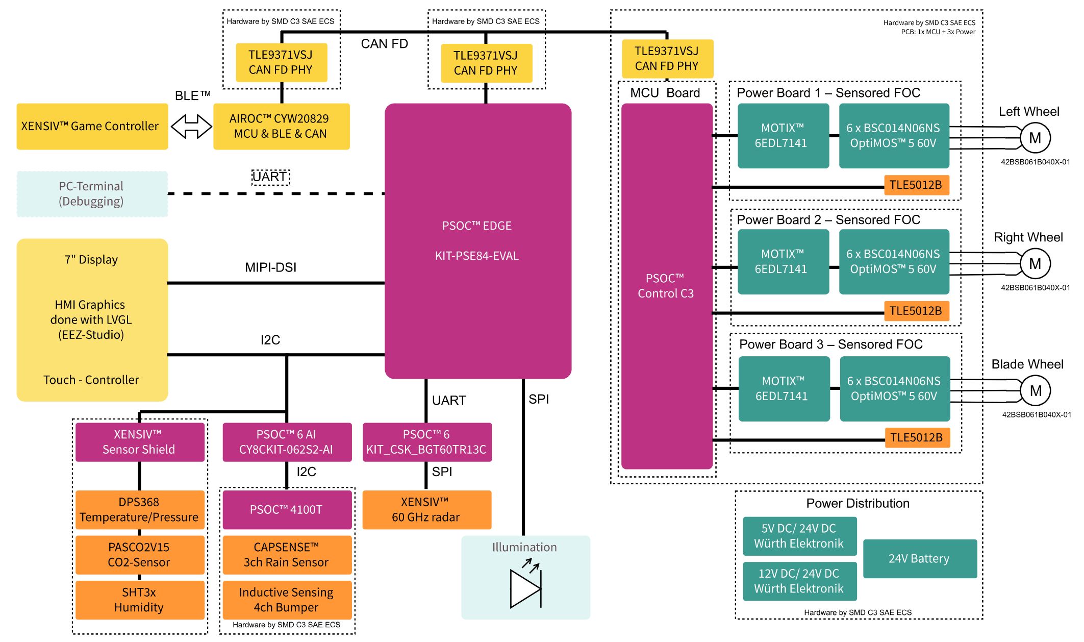
Block diagramMainly officially available boards from Infineon are used to compile the electronical body of the vehicle.
In some cases, e.g. Motor-Control and Rain Sensor, customized PCBs have been designed to fulfill size constraints.
The overall system can be split into the following sections that will be described further in detail:
- HMI including Visualization, and Illumination
- Communication
- Remote Control
- Motor Control
- Radar Sensor
- Rain Sensor
- Additional Sensors
- Mechanics
- Software
The overall central unit is built on top of a PSOC™ Edge E84 microcontroller device - the next Generation of ML Enabled MCUs High-Performance / Low-Power fully integrated microcontrollers with advanced ML hardware acceleration and Graphics. A 7 inch touch display enables human interactions where nearly all features of the vehicle are supported:
- Visualization of the general system
- Visualization of sensor values
- Manual control of the motors
- Illumination
The Light and Versatile Graphics Library (LVGL) is used together with EEZ Studio for designing the Human-Machine-Interface (HMI). Some screens are shown here for reference.
Further 18 pcs of WS2812 LEDs have been built in to show some illumination effects, probably more for fun, but also 'critical' situations like active bumpers can be visualized by different colors.
CommunicationSystem bus
As in many commercial products - not only in the automotive area - a CAN bus has been implemented for the main communication between the BLE Remote Control, Motor system and the HMI unit. All of the used devices support the newer CAN FD interface. When not available on the relevant boards, an external PCB for the PHY has been used, CAN FD Shield TLE9371VSJ
Sensor interfaces
The connection with the sensors is done mainly by I2C or UART interface as shown by the block diagram at the beginning, and will be described in each dedicated sensor section below.
Remote ControlBeside of the on-vehicle HMI, the robot can be remotely controlled via Bluetooth Low Energy (BLE) based on the high performance AIROC™ CYW20829 device with robust RF performance and 10 dBm TX output power without an external power amplifier (PA) using the CYW920829M2EVK-02 evaluation kit. Although the BLE device supports the CAN / CAN FD interface, unfortunately a CAN PHY cannot be found on that board. In this case an external CAN FD Shield based on TLE9371VSJ has been used to bridge the BLE messages to the robot's internal bus.
The XENSIV™ - Bluetooth® game controller is used as remote-control unit and supports all features to move the robot, but activation of additional features, too.
It uses magnet sensors and switches as well as CAPSENSE™ touch technology for a modern open source game controller unit, as it has been already shown in the Game_Controller_BLE_to_CAN_and_Display article.
- CYSBSYSKIT-DEV-01 PSOC™ 63 MCU and BLE transceiver module
- TLV493D magnetic 3D sensor for Joysticks and rotary triggers
- TLV4964-2M magnetic switch for Linear triggers
- CY8CMBR3116 CAPSENSE™ MBR3 for Buttons and proximity detection
- TLE75008ESD SPIDER+ for Multichannel LED and motor driver
This project demonstrates the capability of the PSOC™ Control microcontroller family, specifically the PSOC C3 Main Line, to control three BLDC motors simultaneously with a single microcontroller. Two motors of type 42BSB061B040X (24 W, 52 W, max 4000 rpm, 0.125 Nm) are used for the driving wheels and one 42BSB041B040X (24 W, 26 W) for the simulated rotary mower. Although these might not be the right motors for that type of application, the setup effectively showcases the more complex multi‑motor control capability of the PSOC™ Control family.
Dedicated PCBs (MCU + Power) have been designed to be smaller than the official evaluation boards of PSOC™ Control, enabling a compact integration in the vehicle’s footprint.
The system is designed in a modular way, with two PCBs interconnected by a compact flat ribbon cable (1.27 mm pitch) to minimize space while providing a higher pin count for signals and power. The architecture uses one shared 24 V DC bus for all motors. Power enters through a single connector on the MCU board and is forwarded to each Power board; the 3.3 V rail for the MCU is typically generated on the Power board and fed back to the MCU board, with the option to generate 3.3 V locally on the MCU board using an on‑board regulator if required by system integration.
The complete three‑motor setup consists of one MCU board and three identical Power boards. Each Power board integrates one MOTIX™ 6EDL7141 smart three‑phase gate driver and six OptiMOS™ BSC014N06NSSC MOSFETs, forming a three‑phase inverter (three half‑bridges) for a single motor. Current sensing is implemented with low‑side shunts: three shunts are placed on the board, each 10 mΩ, and the FOC algorithm uses two phase currents; shunt voltages are conditioned by the internal amplifiers of the 6EDL7141. Mounted on the Power PCB, the XENSIV™ TLE5012B sensors provide magnetic position feedback via SPI or IIF/MOTIF and route these signals to the MCU through the ribbon cable. They share the same 3.3 V rail as the MCU, and angle readings are used directly without additional filtering.
A single shared fault/error line from all Power boards is routed to the MCU, if any motor reports a fault, the control system stops all motors prioritizing safety.
The MCU PCB contains the PSOC™ C3 Main Line microcontroller and uses UART or CAN FD for external communication.
Two motors are used for the driving wheels, and one for the simulated rotary mower. Although these might not be the right motors for that type of application it demonstrates the more complex capability of the PSOC™ Control family.
Dedicated PCBs (MCU + Power) have been designed to become smaller as the official evaluation boards of PSOC™ Control.
The mechanical integration is straightforward: a diametrically magnetized magnet is mounted on the motor shaft and aligned to the XENSIV™ TLE5012B. As shown in the evaluation setup above each motor has its Power board screwed to the back of the motor, and one motor carries the MCU board on top of its Power board to minimize harnessing and footprint.
All three motors are controlled using a sensored field‑oriented control (FOC) algorithm with a 20 kHz control loop. Magnetic rotor position is measured with XENSIV™ TLE5012B sensors: Two motors provide position via SPI, and one motor provides position via the IIF interface due to the microcontroller having only one MOTIF interface. Inside, the software control architecture is organized as three parallel FOC instances, each including Clarke/Park transforms, PI current control, inverse transforms, and PWM duty cycle generation.
PWM carriers are center‑aligned at 20 kHz, and duty cycles are updated every control cycle. The main clock is shared and synchronized across all PWM timers for all three motors. A timer in the PSOC C3 generate interrupts which triggers the control tasks and sensor reads so that position and current align with the PWM carrier. Floating‑point math is used for the FOC loops, with all three motors active at 20 kHz, the observed CPU load is approximately 37%. Protections include over‑temperature monitoring handled by the 6EDL7141 gate driver and a software implementation for over‑current response when any driver asserts a fault.
Radar SensorSurface Detection using a 60 GHz Radar on its related KIT_CSK_BGT60TR13C evaluation kit is implemented using DEEPCRAFT™ AI to identify whether the robot moves on grass.
The outdoor environment presents significant challenges due to the wide range of surface types. To address this, we have collected a substantial and diverse data set, as outlined below. Standard signal processing algorithms used to extract to features of different surfaces, as we have observed raw data is quite prone to even small changes.
We have trained a quite small 5 layer Fully connected network with <8000 params to do the classification. We have reached >95% accuracy on the trained model and deployed it to PSOC™ 6 using DEEPCRAFT™ Studio. It is used to convert the *.h5 model to C code to deploy the model on PSOC™ 6 microcontroller.
Up to 10 predictions per second can be done by using a PSOC™ 6 microcontroller. The current model can differentiate grass from most common non-grass surfaces, like gravel, sand, asphalt, earth, stone, cement, metal mesh/manhole/grid. It's robust against any ambient light (direct sunlight, no-light) and low-visibility conditions (foggy, rainy, wet/dirty cover). Additionally, obstacle and cliff detection can be included.
The project uses 29 Kbytes Flash memory with model and complete code size.
Rain Sensor (CAPSENSE™)Using CAPSENSE™ technology a simple implementation of a rain sensor is done. The machine learned model allows to detect between touch by finger, and water drops or rain (respectively water level). Of course, the current implementation does not (yet) claim to be a commercial sensor, but allows evaluation of the capacitive touch technology (CAPSENSE™) and machine learning. We’re using the influence of water on the capacity and sense the different impact of a finger touch and water at different frequencies to distinguish between a wet surface and a touch and even be able to detect the touches on wet surfaces. The sensor gets sensed by a custom PSOC™4100T board which is streaming the data over I2C to a PSOC™ 6 based CY8CKIT-062S2-AI kit which runs a simple ML model as part of our DEEPCRAFT™ Edge AI Solutions. It was created and deployed using DEEPCRAFT™ Studio, where the model can be found and improved as a starter model. The data is sent directly over USB to the studio, which simplifies the collecting and labeling of the data.
Additionally, a grass-moisture sensor is under planning.
Additional Sensors (CO2, Temp, Pressure, Humidity,...)The XENSIV™ Sensor Shield enables developers via the Arduino UNO interface to quickly evaluate and develop with environmental sensors. It also features a TFT display 160 x 80, an OPTIGA™ Trust-M secure element, and a QWIIC connector for additional peripheral expandability.
- 60 GHz Radar XENSIV™ BGT60LTR11AIP
- PAS CO2 Sensor XENSIV™ PASCO2V15
- PDM Microphones XENSIV™ IM72D128V
- Pressure & Temperature Sensor XENSIV™ DPS368
- Security OPTIGA™ TRUST M SLS32AIA
- Humidity & Temperature SHT3x
- 6-axis IMU BMI270
- 3-axis Magnetometer BMM350
- Display 0.96-inch, 160 x 80
Currently, the GUI on the robot shows the values of CO2, Temperature, Pressure, and Humidity over the last hour.
MechanicsWhile the base acryl platform is cut by laser, most other mechanical parts are 3D-printed. This allows to modify and easily adapt new features, sensors, etc. For the prototype PLA filament is used, just for both tires TPU material has been used.
Some 3D views of the robot are shown below:
Additionally, here the individual 3D-printed parts (in alphabetical order):
Obviously, each of the hardware module described above requires its own firmware. Each project is attached to the article and can be used as a reference. Please refer to the included software disclaimer, especially consider that it is PROVIDED AS-IS, WITH NO WARRANTY OF ANY KIND, EXPRESS OR IMPLIED, INCLUDING, BUT NOT LIMITED TO, NONINFRINGEMENT, IMPLIED WARRANTIES OF MERCHANTABILITY AND FITNESS FOR A PARTICULAR PURPOSE.
The following chart shows an overview on each firmware and the interaction between the used hardware boards.
- Size: 63 cm x 37 cm x 23 cm
- Weight: approx. 7kg
- Material: PLA, TPU, Acryl, Silicon
- 3D-printing: 51 pcs, 80 hrs, 2.6 kg
- Battery: 24 V /2 Ah
- Current: approx. 1.5A (including Motor)
- Motor: 24V, 52W, max 4000 rpm, 0.125 Nm
- Gear: 15 : 180
- Wheel: 205mm (Back), 90mm (Front-Dummy)
- Speed: max 3.2 km/h (1000 rpm)
- Software: Over 3800 lines of user ‚C‘-code,
- Costs: 300€ (Material only w/o Electronics)
- Working hours: Don't ask ;-)
This BOM is not complete but lists major important parts:
- Infineon XENSIV™ Bluetooth® game controller
- Infineon PSOC™ EDGE E84 Microcontroller
- Infineon PSOC™ Control C3 Microcontroller
- Infineon AIROC™ CYW20829 Bluetooth Microcontroller
- Infineon PSOC™ 4100T Plus / CAPSENSE™
- Infineon PSOC™ 6 AI Evaluation Kit / DEEPCRAFT™ Studio
- Infineon TLE9371VSJ CAN FD Transceiver
- Infineon MOTIX™ 6EDL7141 Gate Driver
- Infineon OptiMOS™ BSC014N06NS MOSFETs
- Infineon XENSIV™ TLE5012B Magnetic Angle
- Infineon XENSIV™ BGT60TR13C 60 GHz radar
- Infineon XENSIV™ Sensor Shield
- Infineon XENSIV™ PASCO2V15 CO2 Sensor
- Infineon XENSIV™ DPS368 Pressure/Temperature Sensor
- Würth Elektronik 173020536 MagI³C-FDSM (24 V to 5V) Regulator Module
- Würth Elektronik 173021236 MagI³C-FDSM (24 V to 12V) Regulator Module
- AISLER printed circuit board (PCB) of CAN FD Shield TLE9371VSJ
- 3xmotion 42BSB061B040X BLDC motors (2 pcs for the wheels)
- 3xmotion 42BSB041B040X BLDC motor (1 pc for the blade)
- Aftertech® Battery Pack 24V, 2000mAh, Lithium, 78x55x29mm
A very special THANKS to the whole project-team!
Special thanks to Aisler for manufacturing some PCBs and to Würth Elektronik for providing some collateral parts.
This project of a "Sensor Robot for Radar Surface Detection" demonstrates the usage of several Infineon components like microcontroller-, communication-, power- and sensor-devices as a reference, hint or idea for your project.
Go ahead and realize your idea! Stay safe!
Well - that's it!... for the moment. Stay tuned!
Johannes, Achim, Onur, Okan, Gioele, Marco, Michael, Elias, Caio, Sheng, Prajani, and Holger


Comments