


Hardware components | ||||||
| × | 1 | ||||
 |
| × | 1 | |||
 |
| × | 1 | |||
 |
| × | 1 | |||
 |
| × | 1 | |||
 |
| × | 1 | |||
Software apps and online services | ||||||
| ||||||
I am stewing over a clock project. It has been on my bucket list of projects to complete. I have made a couple in the past, but simple and using 7-segment displays. I have some perfect parts for new, big, analog’ish-looking, one; but before I get moving on telling time with LEDs a quick sidebar. I haven't used a Real Time Clock with an ItsyBitsy. or CircuitPython. I have with an Arduino, so I figure it can't be too far off. I am using the wiring and code from my last ItsyBitsy project, ItsyBitsy JoyDraw.
In the end I want to be able to set the time on the RTC, and then display the date and time onto the OLED screen. While the OLED screen will not be used in the final project, is provides a quick and easy way to check on the results. And is useful as a clock on the desk while I work on the larger piece.
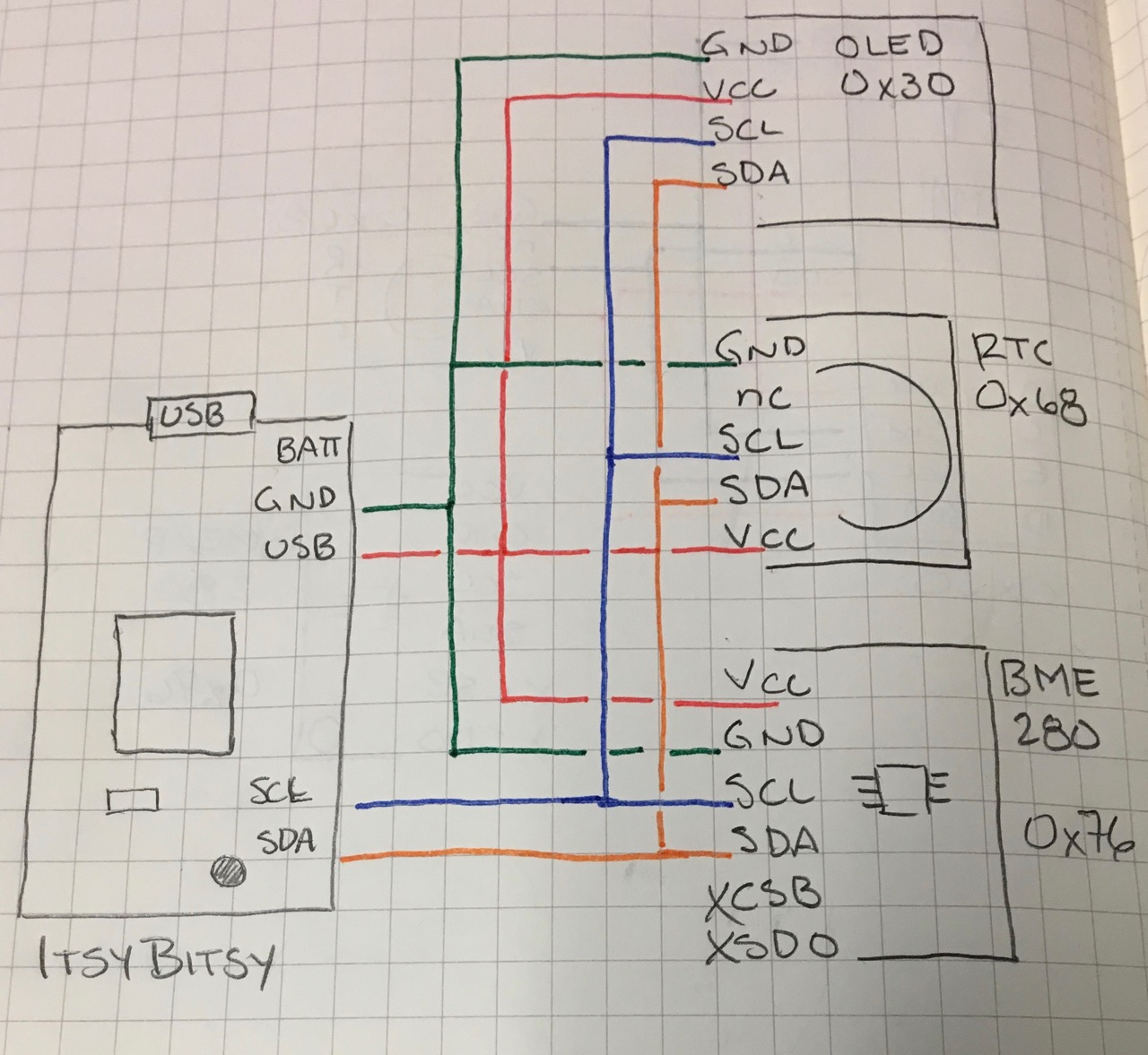
Putting it togetherThe wiring as shown above is pretty simple. Both devices, the RTC and SSD1306 use I2C to communicate with the IB4M. Each device is provided an address. It is important that no two devices have the same address or the data will be wrong or not there at all. As seen in the schematic below, the address of each device are written down to be sure. The address for the OLED is 0x30 and the RTC is 0x68.
Then both get power and ground. A note, when I had OLED alone with the IB, I had to add 2 x 10K pull-up resistors. When RTC was added they were no longer needed. The SCL and SDA pins are labeled on the IB board. They are in the general location as in the schematic above.
I was a bit worried about the power, but as I wasn't using anything that sucked up a lot, all of the devices were run from the USB (power) pin on the ItsyBitsy. I still want to measure and see how much is used overall.
In the code section there is the simple, simple clock. It reads the time from the RTC and prints it out to the screen. In order to accomplish this specific libraries are required. Make sure the following are copied into the lib library on the CIRCUITPY. Time, board, adafruit_ssd1306, busio, adafruit_ds3231. Three of them are pretty self-explanatory; time, _ssd1306 and _ds3231. Of the other two, board is used for various board / pin configurations and busio deals with the I2C communication.
Once the time is read, it is printsed to the serial console. This provides a method of debugging when first trying out some new code. The statement will be removed when it comes to production time.
Having some extra time to kill and since I did have a spare temp sensor with me, I wire up a BME280. It also uses I2C for communication was it was a quick addition to this little project. As one adds more I2C devices to the chain addressing must be looked at. The address of the BME is 0x76, so all of the devices in this chain are unique. Usually you can change them on the hardware by adding a resistor or in software as well.
The adafruit_bme280 library is added to the lib directory. If the local pressure at sea level is added, elevation can also be calculated.
Now that I have some basics down, I am off in search of 80 WS2818 LEDs, some copper magnet wire, and an afternoon of coding. I will be back with the finish creation soon.


Comments