

Hardware components | ||||||
 |
| × | 1 | |||
| × | 1 | ||||
| × | 1 | ||||
| × | 8 | ||||
 |
| × | 1 | |||
| × | 8 | ||||
Software apps and online services | ||||||
| ||||||
| ||||||
| ||||||
Hand tools and fabrication machines | ||||||
| ||||||
Still trying to find my blueprints for it (I think its on my Ubuntu box, but my monitor is fried on it, grrr, and I'm sure its not accessible on FTP, I'm on my Windows 10 workstation now), but here is an interesting example of MOSFET motor speed control via GPIO or PWM.
Obsolete: commercial ESC (electronic speed controls) are so low cost (about $5 per) and ubiquitous that building a controller from regular MOSFETS is not practical. Use ESC's instead like the SImonK 30A.
The top center part of it is kind of dumb in that I think their point is to use a pot read by an ADC to do the speed control. However I would do it via UART or software instead. However the rest of the circuit is a great example of real motor speed control using an inexpensive MOSFET driven by MCU or BBB PWM.
End of Obsolete
Part 1OK, let me explain what I'm doing here. A lot of you realize that what I'm building here is more of a tiny UAV than a toy drone, but I want to have enough processing power on-board that I can do whatever I want.
How its different is my design philosophy in that what I'm trying to do here is shift the majority of my work to a software domain from a hardware/power one. I'm just going to breadboard and build the drone, but all of my flight control will be done with TCP/IP stack with the processor running a service daemon that provides the guidance I'm looking for.
It will be based on a force-moment-mass model based on empirical tests (and weighting the darn thing) that will formally implement a drone control that is smooth, scientific and possibly autonomous that is 100% done in software (based on SENSOR and ACTUATOR section in the physical design). In other words, it will be sweet once finished, capable of long-range semi-assisted flight. I'm thinking of integrating 4/5G data (via USB model model) but only pushing across limited numeric data (caching its video) to keep my usage within plan, but I hope to be able to send a command that will return (via FTP over 4/5G) a nice compressed JPEG still whenever I want to see a location.
I'll just pull the saved video off via manual FTP via wifi once it comes back into range, or just popping the SDCard on the cam itself (which might made more sense, though less techy).
Getting close to that time I need to start ordering stuff from mouser but I need to get a complete BOM together for the physical stuff.
I'll keep you guys in the loop on this one (as a lot of the issues I'm solving are directly related to your projects like voltage conversion) but I want to warn people that the final result may not be open-source as I might choose to release it as a boilerplate commercial version. However I can still make notes here to help in your own projects, and you can shadow my development and processes to develop your own (possibly open source).
Part 2OK, just got my BBBW wireless acquiring well over about 200 feet (indoors) and about 400 feet (outdoors) so I have enough of a wireless tether to actually fly my drone. Very impressed with this little unit (the BBBW); I was a little concerned over the little antenna but they seem to work nice.
Next step is to integrate my MCU6050 inertial unit to it via P8/9 I2C (only interface on it). Its a 6DOF that I got from Hong Kong for about $5 free shipping, its on a break out board and even has an "attitude engine" on it. Why this is important is that back in the day, iMEMs stuff like piezo gyros and accelerometers were only 1DOF voltage-out, but this one not only has the ADC's onboard, they are controlled with their own MCU that calculates to x, y, z, vx, vy, vz, ax, ay, az, tx, ty, tz and I think even rate) and allows the host (in this case the directly connected BBBW) to just receive the actual data we need.
If you want to experiment with the MCU6050 it is 3.3v so compatible with the BBBW right out of the box, uses I2C and only $5 total on eBay (just search on the part number) comes mounted on breakout board with 0.1 header (like SIP) that you just solder on. I'll post up here as I have successes with interfacing it. I can also provide download locations for my tablet-based drone remote (windows installer) as well as code example on the NEO6M, PIC and MCU integration.
I wanted to go nuts with external MCU's but now I'm thinking that I'll have a 3.3V domain and a 5V (TTL) domain on my power section so I'll get my PIC (5V) doing the PWM for the motor speed control. It will have 8 motors counter-rotating per pod (I think I might have a sweet way of controlling yaw through coordinated power throttling). So I'll be able to finally use my bootleg K150.
I'm thinking maybe voltage divider (resistive... I'll put up some sweet discrete networks here so we have some reference designs to bridge cheaply and small-ly between the two voltage domains and others) to translate signals from TTL (5V) down to 3.3v (we did this with RS232 with the PIC for years and years now), and an led-heatshrinktube-phototransistor from 3.3v up to TTL (5V) forming a tiny single line/single direction opto-isolator.
Actually scratch that, here is a $0.18 jobbie that does exactly the same thing. Looks like optocoupler will do it if I can keep the discretes count low.
Part 3Here is my autonomous flight planner (so its a little more than a drone).
This is my "map editor" where I read in a Google Earth map and what I do is I calibrate it for 2D cartesian in meters around an origin (in this case Central and Van Buren downtown) and then I calibrate it by clicking two points on the map I know the NEMA coordinates for (which Earth just gives you by pointing and clicking).'
Then I go to my actual flight planner window and I click on the points in my flight path, and set the altitudes for each waypoint and feed it to the BBBW via FTP (its a pretty big file). I just hit the Waypoint button on my drone remote and it just runs the program, so its a good way to fly out of wifi range. I then get someone with an identical tablet to "catch" it when it comes in range, and it would be manually landed, or just the autoland feature that just nulls everything out and causes it to descend slowly enough that it doesn't hurt the drone when it touches down.
It was interesting doing this because you need to set a 3D radius from each waypoint point because it never actually hits the point (more of a sphere of a preset diameter) that once is passes through this imaginary sphere then it knows to go to the next sphere or point.
It also has my environmentally sealed Emerson camera (that I still need to get an SD card for) that is just bolted to the underside of the base board that I just manually hit the video record before taking off. When I get some video I'll post it here.
Part 4OK (laughing my ass off). Do you guys want to try out the drone remote? Its not done yet, but I have a windows installer for it.
You can run it on Windows 8/9/10 but if you have a Windows tablet, install it (it just uses' VB.NET's stock installer so it should come right off on an uninstall).
Right now all it does is let you push the buttons but it also reads the controls and it normalizes them (little numbers in the title bar). Kind of mess with it a bit to see if its good stuff. Also, you can't use both thumbs at the same time you have to kind of alternate on throttle and stick. Its a fun little beasty.
I've managed to successfully test my BBBW to Win10 tablet wifi connection and its pretty solid with quick acquire. I'm actually thinking this thing will work. I just use socket to shoot over the stacks. Works great, lmao. :D
http://www.mediafire.com/file/hj7q3ym409ip6yt/DroneRemoteInstall.zip
OK someone download it and try installing it. Let me know if there are any problems and I'll get to correcting them. Lmfao seriously put it on your tablet. Its cool as heck.
Addendum 6/18/18
How to use 3-Phase Drone Motors in Real Life:How to program the necessary PIC to feed control signals from the R-PI/Beagle via UART serial to the ESC's (via PWM) that control the motors.
(Check the Inet for an existing preprogrammed PIC (or other MCU) that does the UART In to 8-channel PWM out. There might be one out there.)
Thinking of sticking with just a single 5VDC domain (instead of multiple ones) and just using the onboard VR to run the SBC at 3.3V and then pushing the signals up or downhill like this:
Ok where I'm at on this project is after drowning in datasheets and noticing that my drone would look like a porcupine with all the traditional MOSFETs hanging out of it, I switched over to commercially available ESC's (which are basically MOSFET driven anyways).
Check on EBay for super-cheap jobbies out of China or Hong Kong or somewhere.
Still planning on using a PIC (switching over to a PIC16F88 because of its integrated peripherals) to which I'm going to put in a generic UART In to 8 PWM out using a software loop (not the integrated PWM on the chip) and just count the clock cycles. Have everything for this, just am dreading working with PIC assembly language again (MPLAB is still free so just get a bootleg K150 off of eBay and you are ready to go).
Also dreading the I2C and SPI integration on some of my sensors, so I might bit-bang with a glue PIC and then just feed it out somehow back to my R-PI or Beagle via UART. Looking forward to the coding of the actual brains of it though (UNIX C....command line...super-fast).
OK here is a link to some of the technical on this: http://beagleboard.org/discuss?place=msg%2Fbeagleboard%2Fu4DWGfn6q3U%2FP2D9hfF_DQAJ
I have a force-moment-mass model with some really rough code on it I think in this thread. Poke around Beagleboard for it as it might make a good starting place to start coding a UAV-style drone in that it treats the drone like a computer model with integrating its pitch/yaw/roll moments of inertia (i.e. how difficult it is to spin around its C of G), its mass distribution and the forces of its propellers and gravity), so you can code in C on your controlling SBC.
Its all set up like man-lego in that I talk about the components (hardware and software) but its up to you as to how you build yours!
Addendum: here are some rough notes with some things I've found out that may or may not help.
Firstly when using LiPo's or NmH batteries (what I'm using) its appearing that the 1KV motors (perhaps the most ubiquitous kind) are better for RC plane type drones than quadcopter drones. I'm currently thinking that I need to upgrade to the 3KV versions to get my quadcopter design "off the ground". However you can re-use the 1KV motors for a really nice trust on plane types.
You can't run multiple 3-Phase drone motors off of one ESC (I matched the Amps on the ESC to the motors to start). While useless in flight, I was thinking of doing this for testing, and IT DOESN'T work. It just goes ting-ting-ting (no rotation) on all 4 motors. :(
The best motor mount I've found so far is to use no motor mount. Let me explain. What you do is you chisle (I'm using wooden dowel) out the ends of motor arms and you just machine screw the included motor mount hardware directly to the flattened surface. If you do it exactly right, its structural integrity is sufficient.
What I do for a quick test is grab two of the arms and quickly rotate it with my arms around its central axis; if the arms hold, you have a winner.
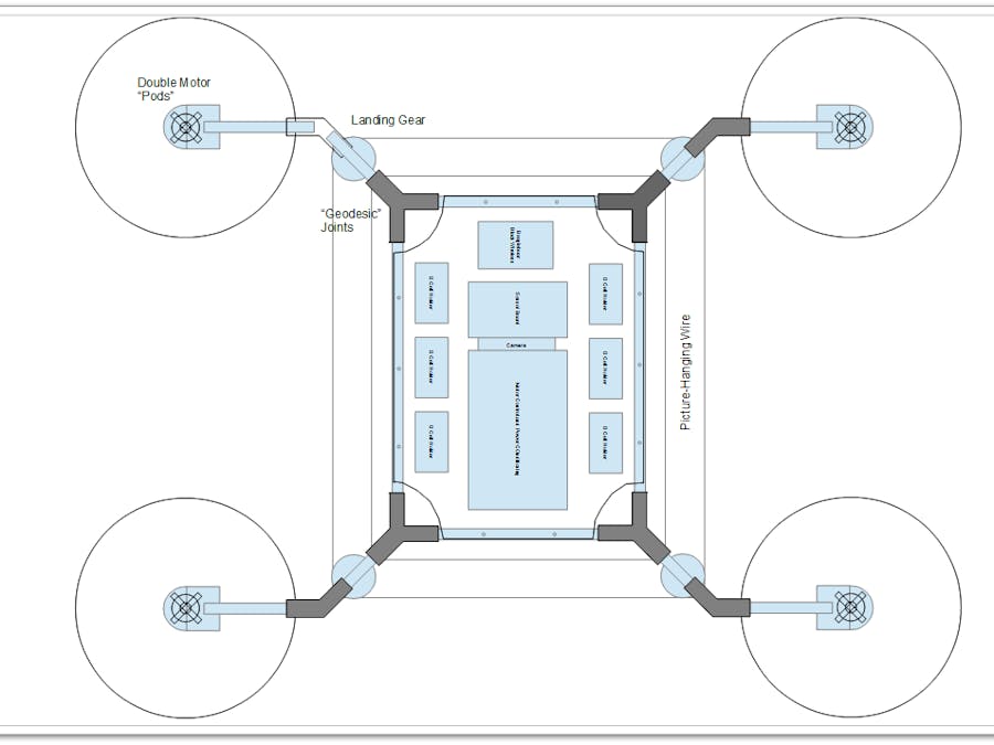
Having some success with "struts" (or in this case "cabling" or "ties"). There was a bit of play in the joints under flight stresses so I strung some picture-hanging wire in tension to the landing gear and the motor arms (geometrically) that took that play right out of it and translated it linearly across the entire drone frame.
Important Design Change: I was going to develop a 3-Phase Motor ESC from first principles with regular MOSFETS but found it a lot cheaper to use off the shelf SimonK firmware ESC's (30A version) available on Ebay for about $5 (free shipping) and still using a "glue"-type PIC16Fx MCU to translate a serial commands to the appropriate software-generated PWM that the commercial-available hobby ESC's use to control the motors. This little piece of advice might save you weeks in development.
Implementation Notes: OK, if you mount your ESC's on the drone arms, I've figured out that you should have the boards in your ESC's vertical so when the arms flex that the board's strongest plane is parallel with the plane of the arm's flexion so you don't crack it. in other words, I mount my ESC's on the sides of the arm shaft.
The worst it can do with a bad bend is crack the EVA resin that I applied originally to tack the ESC's to the arms; the ESC would be OK.
I actually afix them with electricians tape so there is a little give in there. They aren't a structural component but they are attached to a structural component so you have to think a little about the stresses and strains, just organically: am I going to snap my little board in two doing....this.
Counter-Rotation on Props
To do counter rotation (having just set up one arm with two motors, opposing each other) is if you think about it logically, both have to be spinning the same way, so when you turn the one motor upside down, its counter rotating. Counter-intuitive I know but think about it and you'll see I'm right.
Make a fist with your thumb pointing up; which way are your fingers curling? Now turn your thumb down and you'll notice that they are curling the opposite rotational way.
To do counter rotation, you need a matched pair of counter-rotating props. The motors are opposing in this design, but both prop thrusts need to go in the same direction (wind down) ergo you need a pair of counter-rotating props that are really cheap on Ebay.
A real prop you can easily figure out which way it thrusts. The higher edge of the prop should be the leading edge when rotating.
REALITY CHECKS!
OK, here are some issues that have come up, and I'll talk about them here so you don't have to make the same mistakes (mistakes take a lot of time and money to correct with this kind of stuff).
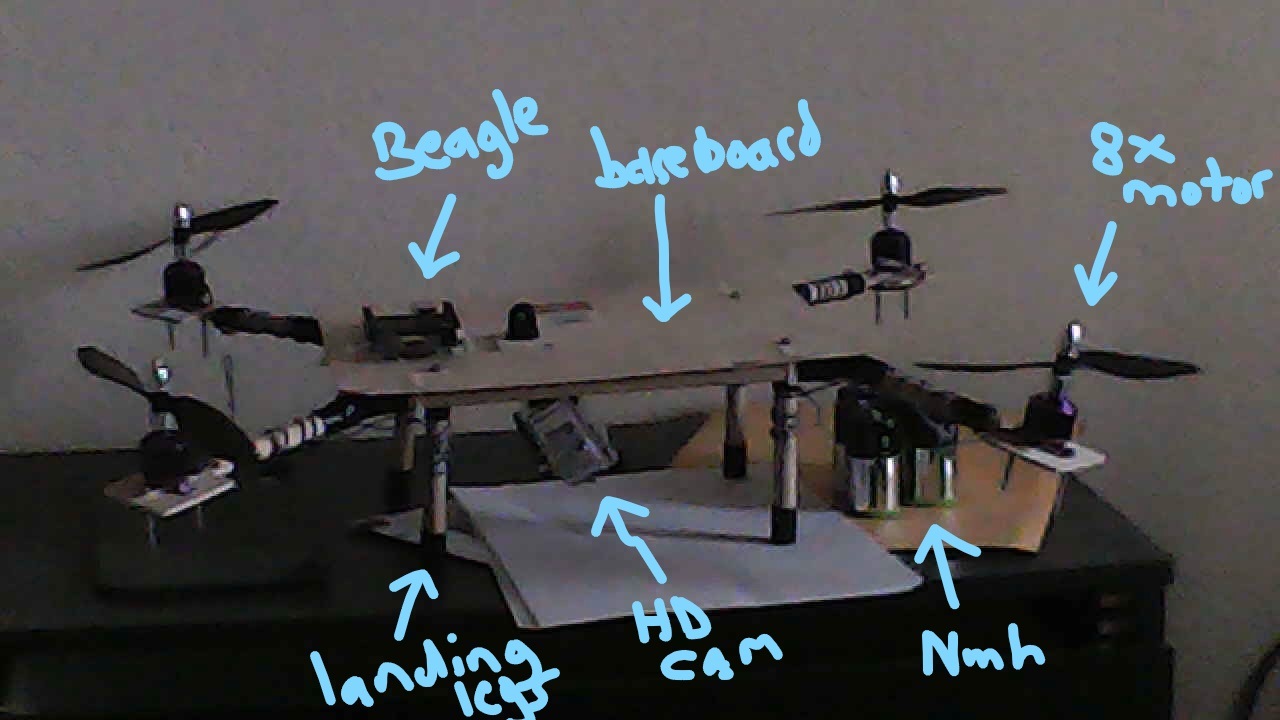
Firstly, let me reiterate what I'm trying to do here. At the end of constructing my physical drone, I want to be dropped right at shell access. What I mean by this is When I mount the sensors (the IMU, inertial measurement unit and the GPS) and connect them via UART (finally found some that communicate serial not SPI/I2C) to the host controller (a Beagleboard Black Wireless in this case), that I will shift the focus of the project to software. You can figure out what I mean by this.
I patch in via SSH over Wifi (BBBW's are set up to do this right out of the box btw) and I program in C to access the UARTs. I really wish some of these smaller operators would stop hording their information...makes a trivial task almost impossible to get done. Have a datasheet for your product...a datasheet is not an afterthought either...its a critical aspect of any serious electronic component. If you want to see what one looks like go to mouser.com and just look at a few. Basically, it has to be useful (PIC manuals are great examples, they just enumerate every function with some focus on points that might be confusing).
Why a Beagleboard?
The original reason why I selected a BBBW is because it has multiple UARTS so its basically got what is called an "octupus cable" already on it. No mutidropping and the nightmares associated with that, you basically just talk (bidirectionally) with COM1-COM7. Shave weeks/months off of building time just by selecting an SBC that has a specific feature.
Wiring motors
Ok, the problem I'm having right now is that my motor wiring is wrong. I thought it out, with the assumption that wire color is consistent so long as its the same model. I was wrong (wow huh). The fix is basic: you just have to wire up every motor to its ESC manually and individually, rotating the wires until you get a good strong rotation (there are weak rotation modes btw, so bring it up to full power!).
To wire the power trains (buses?) on it, I use harvested extension cord about the same gauge as the power lines coming off the ESC. This should insure that all of the stuff I'm adding runs as cool as a cucumber. An ounce of prevention is worth a pound of cure. I decided to use "taps" where you wrap the bus around the baseboard, wiring it like how they wire networks with "rat belts". To do a tap you carefully with an exacto blade go around the wire and then cut longitudinally and remove a short length of insulation from the wire in question.
A lot of design changes here (that I will post) a major one being (and write this down) finding IMUs and GPS modules that communicate via basic serial. Here are the part codes that after MUCH research finally found: the Razor IMU (search on "arduino bootloader ATMEGA" for the "correct" unit) and the "NEO8MN" (has....HAS...to be the N variant!) I'll try to update the project parts list with these new part numbers. The main difference is they communicate via serial NOT SPI/I2C.
A major issue: to build one of these things, you have to understand that you batteries have to conduct AMPS of electricity in order for it to fly. The question in my mind is the electrical/physics realities of doing this...those little battery casings need to be conducting entire amps of current (electrons) in order for sufficient power to be available to the motor/props to lift it skyward. We've all seen drones flying, so we know its possible, but I'm thinking it might be an intrinsically difficult task, one that can (1) either be solved by a lot of trial and error and burned-out parts or (2) careful, mathematical analysis of the volts/amps of each component in the SPECIFIC design. In other words, the answer might be you ammeter becomes you new best friend.
Infinite Range: I'm thinking with the integration of a 3/4G data modem with unlimited data service (found one local, cool huh? :D $50/month I think with Boost Mobile [let me check on that]), that I can not just socket over the required flight data (via TCP/IP) AND I can pass real-time video back (I wasn't going to do this as I could only find limited data plans). As long as it fly's in cellular service areas, this idea might be a very cool part of the project. I'm getting the parts for this soon.
Addendum: talked to the guy at Boost. They don't use SIM cards anymore they just pump in the serial number of the modem in question (should be able to get an inexpensive one off of Ebay). However even their unlimited plan is only 50Gb/month at FULL-SPEED and then throttles down (as per network load) after you pass this point). Ok, Good news: how much video is that? The numeric data you pass is diddly, its the video that can be prohibitive. Regular video is 2/Mb/minute. M-JPEG (taking into consideration its inefficency) still takes 70 hours of continous video to exhaust a 50 Gb plan.
To reduce the complexity of integration, I think what I'm going to do is use a wifi-router style modem and talk to it over wi-fi. However I might still do the USB connection eventually.
Good News: got the output stage of my PIC16F88 S3 8-channel PWM controller coded. I got a virus in my microburn software so I got a new PICKIT3 programmer coming in, so I can burn it and test it. Should have the serial input (UART) on it later on today but won't be able to test/debug until I get my new programmer.
Thoughts on Battery Recharging: lots of ideas on this but the ones that seem practical are the following (listed in order of practicality):
(1) Just put two bolts on the base board that as soon as it lands I just hook-up a automotive-style charger and just wait. I pull the jumper-cable style clips off it and its ready to fly again.
(2) Make the batteries into a pack that can just be physically changed.
(3) (kidding) wire up a bunch of microwave-oven magnetrons all facing up and line the bottom of the drone with microwave diodes and just have it hover above them at 50 m until periodic ADV voltage checks say the batteries are full again.
Right now I just cut the rat belts on the battery holders, pop them out and recharge manually in a Harbour Freight NmH charger.
----
OK, got something together for you guys and gals. I'm developing a PIC chip (called an S3,a mod'ed PIC16F88) that has 8 hobby servo/ESC PWM channels on it controllable by UART/serial. If you want to see what it does, download this:
https://www.mediafire.com/file/7vfzjhkl63dfzu6/s3controller.zip
It has the stock VB.NET installer on it so it should come off clean. It controls up to 8 servos/escs and up to 5 LEDs. I'll post the source code for it somewhere AND the firmware for the S3 itself.
The coolest part about it is you can have multiple instances of the S3 program up at the same time (as many comm ports as you have), driving multiple chips, so you can control up to dozens of servos and stuff at the same time. Just hit Hide Configuration (after setting the comm port being used and you have a ton of sliders on a basic control panel.
OK, here's the video on it (it will have full servo-driven pan/tilt, 1 Mpx, hopefully telephoto. WHy am I not using the Adafruit version? You can't get video serial on theirs (only 1 frame/sec) but if you use a uCAM III their UART goes up to 3.2 Mbps and if you read with a BBBW it also has a 3.2 Mbps maximum on its serial. There are reasons why I'm evaluating it.
Here is how it looks on my PC (going to push the MJPG over sockets over 3/4G if I can).
Fact: just finished figuring out how less efficient MJPG (basically a stream of individual JPG files) is from like MPEG/MP4. Guess what....its only 6x less efficient (and I think I can get it down to about 2x by turning down the resolution). So, managable.
OK, to control my seros and ESC's I have a software-based PWM chip (a programmed PIC16F88) that will convert serial to PWM (with 5 extra TTL out channels). Here is a little video of how I program the chip.
Example of successful GPS data stream from NEO GPS module AND decode to latitude and longitude.
About the REAL reliability of iMEMs gyros and accelerometers (scroll down to ArduIMU video):
https://www.hackster.io/woody-stanford/daedalus-psc-personal-spacecraft-detailed-mockup-bf4f02


Comments