


Lattice recently introduced the MachXO4 FPGA.This is a flash-based small field programmable gate array (FPGA) and supports from 1K to 10K of Logic (LUT’s) in small devices.
The MachXO family has been a round for a very, very long time, and is probably one of the most used FPGA’s ever in the industry. The XO4 is very similar to its predecessor XO2 and XO3, however it comes with an very interesting advantage: It’s supported in Lattice last generation toolchain : Radiant.
Risc-V softcoreThis tutorial is the next step with the Risc-V Demo we build in the previous one. Take a look here for the 5 steps to build a softcore in a Lattice FPGA:
Build your soft Risc-V with XO4 in 5 steps - Hackster.io
In this Tutorial we explore how to build your own IP-packages, usable with the Risc-V soft-core. We make use of online LLM AI models to generate code.
§ IMPORTANT: to make it more readable, I mark actions to take (mouse-clicks, keyboard entry etc) with a task symbol ‘ § ’ at the begin of the line
HardwareThis Tutorial is using the MachXO4 evaluation board : LFMXO4-110-EVN
This eval-boardhas the 10K logic FPGA, and supports multiple IO expansion ports like Raspi, Arduino, Versa, Aardvark. It supports also the ASC-10 Power monitoring chip, switches, buttons, Leds and a 7seg display.Interfacing is via USB : the FTDI chip on the board creates 2 interfaces: one to the JTAG programming interface, and one to the I2C bus interface.We use the programming interface in this tutorial.
Remark: This Tutorial you can run on any Lattice Eval board with FPGA supported in Radiant, at the end its a matter of adapting the pin-constaint file.
Tutorial 7 Steps for creating new IP and Drivers
We follow the following steps:
- 1. Understand the IP Packager
- 2. Using AI for Verilog and the C-Drivers
- 3. Create a new IP package
- 4. Rebuild the System Architecture
- 5. Rebuild the Firmware and load the Memory
- 6. Run the tools and check the Hardware
- 7. Program the Hardware
First check the previous tutorial to have a basic hello world project createdAlso look at the trainings for Radiant, Propel and IP-Packager in the appendix section B
IP Packager (IPP) uses a set of data, collected in a directory as the base for generating the IP package. Its wise to understand the directory structure, so here a view of an IPP-collection
You can start with an empty directory, and IP Packager will use the following structure:
- rtl : your design modules in verilog of vhdl –required
- plugin : your xlm plugins, - optional – not touched in this tutorial
- driver : your c-code driver files – optional – we will use this
- doc : documentation directory – mandatory, and will be populated by IP packager
- backup : automatic created
- .previewResult : automatic created in the process
The result of the IP packages is an IP module that can be used and re-used in the Propel Builder environment. It’s packed into an “.ipx-file” that can be imported into Propel Builders IP Library. This is an example of a possible IP :
Its an module IP block that can have common IO and busses like APB, AHB, I2C and have a functionality with (possible) outputs. This example is an APB memory mapped module that drives a 7-segment display. This is also the example we will create in this tutorial 😊Now close IP packager (if you have it open),
Lets create the IPP directory first :§ Open windows Explorer and create an ‘ip_packager’ sub-directory in your workspace directory, add the sub-directory ‘APB_7SEG’ and create the rtl, drive and doc sub-directories. (same structure as you see in the picture above)
Now lets first create our core IP.
Step 2a : Create RTL code with AIIn place of writing your own code, its fun to play around with some AI LLMs. Not because its always better, but it might save you some time, and create some experience.
Using Large Language models for creating code is interesting. Code language is very strict and bounded, which is ideal for AI models to become precise. The challenge is to have your functionality created correctly, so its all about the prompt !We want to create an IP block that interfaces an APB bus (Slave side) to a 7segment output driver, using a memory mapped address location that convert hex input into the 7-seg drive output.§ Goto Google Gemini (but you can try ChatGpt, CoPilot, Grok or any other your think is good) and try the following prompt:
<Prompt code>
 Create a Verilog module with an Slave APB bus as ' input', mapping one memory address to a register, and create an 7segment decoded output as 7 led IO's. Memory address should writable and readable, APB interface should have an SLVERR that is always low and the 7 segment out put signals are active low.
</code>
Result is well done. I needed one more iteration to add a delay state to the APB read cycle. The result is in the apb_7seg.v file – see code section.
module apb_7seg (
    input wire        PCLK,
    input wire        PRESETn,
    // APB Slave Interface
    input wire [31:0] PADDR,
    input wire        PSEL,
    input wire        PENABLE,
    input wire        PWRITE,
    input wire [31:0] PWDATA,
    output reg  [31:0] PRDATA,
    output wire        PREADY,
    output wire        PSLVERR,
    // 7-Segment Output (Active Low)
    output reg  [6:0]  seg_out
    );
// FSM States
localparam ST_IDLE      = 1'b0;
localparam ST_READ_WAIT = 1'b1;
reg       state;
reg [3:0] display_reg;
// PSLVERR is always low per requirements
assign PSLVERR = 1'b0;
// --- State Machine & Bus Logic ---
// PREADY is high for all writes, but only high for reads after one cycle delay
assign PREADY = PWRITE ? 1'b1 : (state == ST_READ_WAIT);
always @(posedge PCLK or negedge PRESETn) begin
    if (!PRESETn) begin
        state       <= ST_IDLE;
        display_reg <= 4'h0;
        PRDATA      <= 32'h0;
        end else begin
            case (state)
                ST_IDLE: begin
                // Write Logic: Immediate (No delay)
                if (PSEL && PENABLE && PWRITE) begin
                    if (PADDR[7:0] == 8'h00) begin
                        display_reg <= PWDATA[3:0];
                    end
                end
                // Read Start: Move to wait state if a read is requested
                if (PSEL && PENABLE && !PWRITE) begin
                    state <= ST_READ_WAIT;
                    end
                end
                ST_READ_WAIT: begin
                // Access Phase Completion: Move back to IDLE
                // PREADY is now high via the assign statement
                    if (PADDR[7:0] == 8'h00) begin
                        PRDATA <= {28'h0, display_reg};
                    end else begin
                        PRDATA <= 32'h0;
                    end
                state <= ST_IDLE;
                end
            endcase
        end
    end
// --- 7-Segment Decoder (Active Low) ---
// Same mapping as before: 0 = segment ON, 1 = segment OFF
always @(*) begin
    case (display_reg)
        4'h0: seg_out = 7'b1000000; // 0
        4'h1: seg_out = 7'b1111001; // 1
        4'h2: seg_out = 7'b0100100; // 2
        4'h3: seg_out = 7'b0110000; // 3
        4'h4: seg_out = 7'b0011001; // 4
        4'h5: seg_out = 7'b0010010; // 5
        4'h6: seg_out = 7'b0000010; // 6
        4'h7: seg_out = 7'b1111000; // 7
        4'h8: seg_out = 7'b0000000; // 8
        4'h9: seg_out = 7'b0010000; // 9
        4'hA: seg_out = 7'b0001000; // A
        4'hB: seg_out = 7'b0000011; // b
        4'hC: seg_out = 7'b1000110; // C
        4'hD: seg_out = 7'b0100001; // d
        4'hE: seg_out = 7'b0000110; // E
        4'hF: seg_out = 7'b0001110; // F
        default: seg_out = 7'b1111111;
    endcase
end
endmodule
§ Save this file under the rtl sub-directory as apb_7seg.v
Optional you have AI generate a test-bench file. This way you could use the Siemens Questasim for a simulation and verification. File name is apb_7seg_tb.v – see code section
Step 2b: Create C-Code with AINow we create the C-drivers I the same way.
§ Don’ t close you AI LLM, as the Verilog design history will help you requesting the driver creation. I used the following prompt for a driver and an main-example:
<Prompt code>
The apb_7segment module is driven by an RiscV processor. Write the bsp-drivers to support the processor accessing the module in c-code for writing the data, reading the data, and create a main() example to drive the 7 segments in a loop.
</code>
Result is very promising in the first answer. Gemini creates a include.h file defining the functions and the base address,
#ifndef APB_7SEGMENT_H
#define APB_7SEGMENT_H
#include <stdint.h>
// Define the base address according to your RISC-V SoC memory map ie: 0x40000000
#define SEG7_BASE_ADDR 0x40000000
// Register Offset
#define SEG7_REG_OFFSET 0x00
void seg7_write(uint8_t value);
uint8_t seg7_read(void);

#endif // APB_7SEGMENT_H
creates a c-file with two functions,
#include "apb_7seg.h"
void seg7_write(uint8_t value) {
    volatile uint32_t *seg7_ptr = (volatile uint32_t *)(SEG7_BASE_ADDR + SEG7_REG_OFFSET);
    *seg7_ptr = (uint32_t)(value & 0x0F);
    }

uint8_t seg7_read(void) {
    volatile uint32_t *seg7_ptr = (volatile uint32_t *)(SEG7_BASE_ADDR + SEG7_REG_OFFSET);
    // The hardware returns 32 bits, we only care about the lower 4
    return (uint8_t)(*seg7_ptr & 0x0F);
    }
and adds a main() routine as an example.
#include "apb_7seg.h"
// Simple busy-wait delay function for RISC-V

main() {
    uint8_t counter = 0;
    while (1) {
        seg7_write(counter);
        uint8_t verify = seg7_read();
        if (verify == counter) {
        counter = (counter + 1) & 0x0F;
        }
    delay(1000);
    }
return 0;
}
§ See the code section: safe the.h and.c files in de /driver subdirectory.
Step 3 : Use IP PackagerIn this section we use the created IP Packager directory and the generated code files to create an IP-Package (.ipx file)
§ If not opened yet, open Propel Builder and load the tutorial project my_soc, created I the previous Tutorial. You should have this view:
§ Open Tools -> Ip Packager and select ‘file’ -> ‘open ip library’, and open the IpPackager directory that we have created above : <workspace>\ip_packager\APB_7SEG.Once open :§ Select Design files and add: select the apb_7seg.v file from the rtl directory.IpPackager recognizes the module and the IO ports - press OK
§ Select the Misc Section : under Drivers, add the driver files apb_7seg.h and apb_7seg.c§ Select Doc assistant, and fill out your IP information (free text), save it.(§ Optional add the Tech Bench file - if you tested it !)§ Select Meta Data->Basic info and fill out the IP info, be sure to select the platforms
Now all generic data is setup, we have to create a Memory map and the Interface.§ Under Meta Data, right click on the ‘Memory Map’, and add a memory map.
§ Rename this memory map to a suitable name like APB_SEG7_MAP.§ Then add a Address Block, add a Register, add a Register Field – see pictureThe details of the memory-fields are not relevant at this point, but we need to add the map to the APB interface.
§ Right click on Interfaces, and add Interface. Rename it to a proper name like APB_S0then change the interface fields to reflect a target APB bus with the APB_SEG7_MAP selected as the memory map – see picture.
§ Next is to connect the Physical port to the Logical port by completing the Table. See picture. Don’ t connect PCLK, PCLKEN and PRESETN.Save the editor
§ If everything is setup correctly, you can hit the IP-icon, and an IP example is created:
§ Click on Generate and select Finish, an example library directory is created, like it would be done in a real project. Close the open explorer and go back to the IPPackager.!!: If something is missing, you get notified in the console, and/or you can use the design rule checker.
Last step is to create the IP-Package: § Press the Package IP icon, and an.ipk file will be created. This file can be imported into Propel Builder (or shared with others)
Step 4 : Re-Build the System ArchitectureNow go back to the Propel Builder schematic overview.
We going to add the created IP to our IP catalog.§ Select the tab IP Catalog (lower left part of the screen next to Design View.You see all the Local IP. (If desired, you can also look at IP on the Server)At the top of the IP Catalog section, there is a download icon (Icon with a greed down arrow), press it, and browse to your IP
§ Select the.ipx file and open. Accept the Licence Agreement.Result is a new IP in the list of the IP Catalog (under the name you used to create the IP Package). Its called APB_7SEG.§ Double click it to add an instantiation to your design:§ Define Component name : ‘ seg7’ (names can’ t start with a number).§ Press Generate§ Press Finish§ Press ok o the Instance Name window
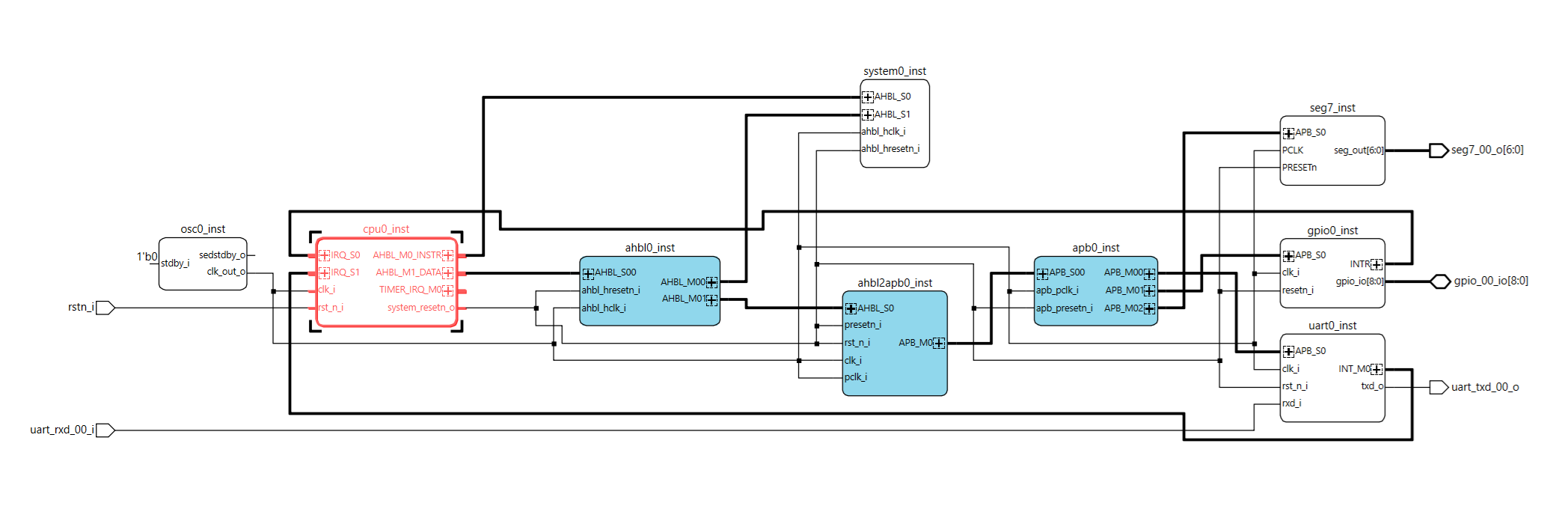
This is the result :
§ Connect the PCLK to the Clock network, connect the PRESETn to the reset netwokThe Slave APB bus needs to be connected too, but we miss a 3rd buss on apb0_inst,§ Double click on apb0_inst and increase the Total APB Completers to 3, Generate§ Connect the APB bus to the peripheral
We need to create the IO for the 7 segment outputs : § Right-click on an empty spot, and select ‘Create Port’§ name it ‘seg7_00_o’, make it an output, set Bus options MSB:6, LSB:0§ connect the IO to the output of seg7_inst
Almost there, now look at the Address view. You see the seg7_inst/APB_S0 assigned an 1K address block – this is ok.§ Just lock the address by clicking on the open box (blue marker appears)
§ Generate the system (press on the generate button), and save the design
So: We rebuild our system architecture, and added a 7-segment memory mapped interface !
Step 5 : Re-Create the FirmwareLets adapt our firmware to drive the 7segment display.§ In Propel builder, click on the Propel SDK icon and open Propel SDK§ Select your workspace, press launch
! Propel SDK will try to setup a new BSP as we launched it from propel Builder.We could do this, and you start with a clean design, howeverThis is not needed, as we already have a software project from the previous tutorial, and any changes you have done would be nice to keep.
§ Press cancel, and in the project explorer open the src-section.§ Double click on the ‘sys_env.xml’, and you see the current platform overview:
As you can see, this project is not using our new created architecture.We can update this project, forcing to use the new sys_env.xml:
§ Goto the menu, select project -> update Lattice C/C++ project§ Browse to you new xml file, its in <workspace>/m_soc/sge, open ityou see in gray the new BSP driver info.§ Mark ‘ Update BSP Driver Information’§ Mark ‘ Regenerate toolchain...’ and press update
Some key changes: - We have a new driver directory ‘APB_7Seg’ with out.h and.c code files - Toolchain is updated to take the new drivers into the compiler-list - The sys_platform.h is updated with the Memory map for APB_7SEG: #define SEG7_INST_BASE_ADDR
/* ip instance base address */

#define CPU0_INST_NAME "cpu0_inst"
#define CPU0_INST_BASE_ADDR 0xffff0000

#define SEG7_INST_NAME "seg7_inst"
#define SEG7_INST_BASE_ADDR 0x40000400 // <----------------
§ Action: open the apb_7seg.h file, and change the base directory into the SEG7_INST_BASE_ADDR defined address (ie 0x40000400). Save the fileOur driver is now up to date to work with the right memory map
Last thing we need to change is our main.c, to include the 7seg example loop that AI build for us in an example. The Seg7 peripheral does not need any initialisation, its plain memory mapped, so we can adapt the main.c as follows:
Add #include "apb_7seg.h" to the include definitions (line50)Add seg7_write(idx); to the main loop – (line 120)
§ Make this changes, or copy-past the main.c in the code-sectionSave all files, build the project – hopefully everything should be ok
§ Go back to Propel builder, and re-generate the system memory with the new firmware (see previous tutorial). Save project§ Click on Radiant to start the tool
Step 6 : Create the HardwareWe are back in the main too Radiant. Before we can generate the bitstream, we have to update the pin constraints, as we have now 7 more IO’s that we need to drive.Looking at the MachXO4 eval board schematic, you see the following :
The 7 segments (basically we have 8, but we don’ t drive the dp / dot), are connected to Bank5, and we have to add the connections of seg7_00_o[6:0] to our.pdc file:
######
## XO4 LED 8 SEGMENT a,b,c,d,e,f,g
######
ldc_set_location -site {G2} [get_ports {seg7_00_o[0]}]
ldc_set_location -site {D1} [get_ports {seg7_00_o[1]}]
ldc_set_location -site {C1} [get_ports {seg7_00_o[2]}]
ldc_set_location -site {D2} [get_ports {seg7_00_o[3]}]
ldc_set_location -site {E2} [get_ports {seg7_00_o[4]}]
ldc_set_location -site {E3} [get_ports {seg7_00_o[5]}]
ldc_set_location -site {E1} [get_ports {seg7_00_o[6]}]
ldc_set_port -iobuf {IO_TYPE=LVCMOS33 DRIVE=8} [get_ports {seg7_00_o[*]}]
§ Copy the constraints and add them to the XO4_pins.pdc in Radiant, save the file.
Now run the Radiant tool-chain to create the bitstream :
Once this is done, we have a bitstream and can program the FPGA on the MachXO4Eval board.If interested: check the Mapper Resource report. It tells you our new peripheral uses only 17LUTS and 9 PFU registers
Step 7 : Programming the FPGAThe created bitstream jedec file is in <workspace>/my_soc/impl_1/my_soc_impl_1.jed.§ Open the programmer from the Radiant tool by clicking the icon.
If you have the board connected, us the “Detect Cable” to see if the programmer can reach the board and talks to the FTDI USB chip. The first USB connection FTUSB-0 is always the programmer interface.§ Take a look at the programming details by clicking on ‘Device Properties’, here you can select alternative bitstreams but also how to program: direct to the config-memory of the FPGA, to the onboard config flash or in other cased program into a separate boot-flash. We select the FLASH via Jtag and direct programming.
§ Select the program icon (green arrow), and the programming starts. You can follow the feedback in the console.Once ready, the board resets (or you can manual reset by button SW2), and the leds should start looping around AND the 7seg display showing the values.In case you have the PC-UART connected to the Versa Pins on X2 pins, you can see the welcome message.
Have fun.
AppendicesA : Lattice Free Toolchain
Goto the Lattice website and create an account. You need this for your free license.Download the toolchain and install the software:Radiant softwarePropel softwareAt the moment of creating this tutorial, we are at version 2025.2.Once installed you need 2 things:
1 Get a License file, login on the Lattice website and go to support-> software licensing->license support center -> request free license: link
Select the Propel license (it includes the Radiant License as well) You prefer probably a node-locked (Mac-address based), select, fill out the form, fill in your Mac-address and receive the email with the license.dat file.remark: the page runs with JavaScript, and is sometimes a bit slow and buggy.
2 Copy license.dat file to the standard license directory for propel (<lscc install>\radiant\2025.2\license), however you can choose any location like the propel install, as long as you set the environment variable to this location – next section
3 Set environment variables to the place where you copied the.dat file :
The SALT variable is needed for the Questasim simulator (we don’ t use it in this tutorial)You can test the license file in the Radiant tool
B: More info onlineMachXO4 landing page with all datasheet and documents
Risc-V softcore (SM version) + Risc-V softcore (MC version)
Training videos on the MachXO-series
Propel training video + Lattice Insights


Comments