

Hardware components | ||||||
| × | 1 | ||||
| × | 1 | ||||
| × | 1 | ||||
| × | 1 | ||||
Software apps and online services | ||||||
 |
| |||||
 |
| |||||
| ||||||
Compact I2C devices like gyroscope sensor can easily help you out in the axial monitoring system which detects the parameters and shares it to the user through MQTT and email nodes of Node-RED services.
In this blogtut, we made soae simple but advanced online axial monitoring system using basic nodes of the Node-RED.
Hardware Required- Arduino IDE
- GMAIL
- Node red
For newbies and intermediates can check out the ESP8266 installation and resolution for the issues while installing the ESP8266 from here.
If you are not familiar with Node-RED Installation and using MQTT node in Node-RED, I suggest you to check out my previous blogtut in which I have shared all the detailed information for Getting Started with Node-RED services.
Note: Kindly do not use the I/O and dashboard nodes in the flow page which is used in the previous blog. We have mentioned about nodes which we used in this project in the below discussions.
About Gyroscope Sensor - MPU6000 I2C moduleThe gyroscope sensor has been used a various technical field like automotive, industrial, electronics and many more. It unveils various kind of application in many real-time concepts. Not going very far, even our smartphones consist of gyroscope sensor which specially used to detect the shaking or vibration while using the camera, playing video games, phone rotate etc. Using these sensors, we can increase the stability in various high-tech devices or a specialized anti-skid system.
MPU6000 I2C based breakout board is 3-axis I2C gyroscope and 3-axis I2C accelerometer with full-scale ranges and has the Digital-Output of 6 or 9-Axis MotionFusion™ Data in rotation matrix. The sensor can easily be connected to I2C adapters compatible with IoT development boards like Arduino, Raspberry Pi, Particle, Pycom, etc. and perform the functions by using different I2C libraries available for different programming language on GitHub.
Code- Initialize the Wire.h file called as I2C library especially use in Arduino IDE
#include <Wire.h>
- Initialize the I2C registers of sensor module which is specified to work with 2 wire protocol.
#define Addr 0x68
- Begin the I2C transmission and Initialize the baud rate as per the requirements for serial communication.
void setup() {
 Wire.begin(2,14);
 Serial.begin(115200);
 setup_wifi();
 client.setServer(mqtt_server, 1883); // Initialize MQTT Server
 client.setClient(espClient);         // Esp Client Setup
 }
- Request for 6 bytes of Data which we want to read from the sensor through I2C connection for X, Y, Z axis to read the axis as well as rotation
 // Request 6 bytes of data
 Wire.requestFrom(Addr, 6);
 // Read 6 byte of data
 if(Wire.available() == 6)
 {
   data[0] = Wire.read();
   data[1] = Wire.read();
   data[2] = Wire.read();
   data[3] = Wire.read();
   data[4] = Wire.read();
   data[5] = Wire.read();
 }
- If 2 bytes of data is available then use the mentioned below formula will help to convert the data bytes and display desired values
 // Convert the data for axis (x,y,z)
 int xAccl = data[0] * 256 + data[1];
 int yAccl = data[2] * 256 + data[3];
 int zAccl = data[4] * 256 + data[5];
 // Convert the data gyro rotation
 int xGyro = data[0] * 256 + data[1];
 int yGyro = data[2] * 256 + data[3];
 int zGyro = data[4] * 256 + data[5];
- Manipulate the axis parameters as per the requirement through Sensitivity and resolution settings given in datasheet
 // Axis Data
 float acclX = xAccl/4096;
 float acclY = yAccl/4096;
 float acclZ = zAccl/4096;
 // Rotation Data in degrees per second
 float gyroX = xGyro/131;
 float gyroY = yGyro/131;
 float gyroZ = zGyro/131;
- Using Serial.print you will be able to read the sensor data in the serial monitor screen.
Serial.print("AccelX: ");
Serial.println(AccelX);
Serial.print("AccelY: ");
Serial.println(AccelX);
Serial.print("AccelZ ");
Serial.println(AccelX)
Serial.print("gyroX: ");
Serial.println(yaw1);
Serial.print("gyroY: ");
Serial.println(yaw2);
Serial.print("gyroZ: ");
Serial.println(yaw3)
With the help of MPU6000 Sensor, I have figured out use YAW rotation in the individual axis which used to detect the rotation of the rigid body which changes the direction using mentioned below formula
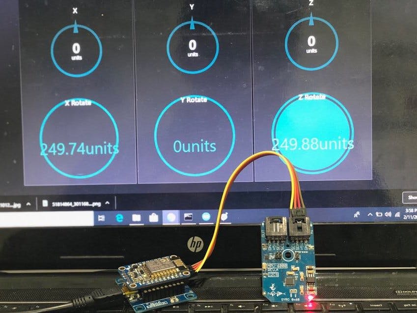
Node-REDAfter working with an above different way to monitor gyro sensor (MPU6000) with Arduino, let's detect the Axial direction and YAW rotation with Node-RED dashboard.
For installation of Node-RED and to install the different nodes in node red in windows operating and to use MQTT please go through the previous blogtut.
In this project, We will be using MQTT, Join, JSON nodes, email in Node-RED dashboard via ESP8266.
JOIN NodeWith help of JOIN node, we can join the output from more than one node at same and using this node we are going to club all the MQTT nodes with different topics
- Open the Node-RED using the command Node-RED in command prompt
- Copy the loop-back IP mentioned in command prompt (Loopback IP:1880) and paste it on Web-browser
- Click on Manage Pallete by clicking top right “hamburger” icon
- Select and drag the Join Node (from the left side of node options) in a flow page.
- Double Click on Join node
- Click on MODE
- Select Manual mode
- Click on the CheckBox of “ and every subsequent message”
- Click Done
- Join all the MQTT node with Join node
Note: You can also set as per your requirement
JSON node will help us to convert the output of different nodes in JSON string which can be further used in many different ways
- Select and drag the JSON Node (from the left side of node options) in a flow page.
- Double Click on JSON node
- Click on Action drop-down and select convert between JSON string & object
- Click Done
Using email output node we are going to send the email alert to the user and using it with node red is one of the best way by just entering the email id and credentials. After drag and drop of email node
- Double click on Email node
- Write Email ID you want to send
- Fill out the user credential in Username and Password Textbox
- Click Done
The Most Importantly using and inject node to write down message to be showed in message title while sending the data in email id and will connect the the inject node with JOIN node only which combines and make one string.
- After Drag and Drop double click on Inject node
- Enter the Topic name what you want to display in the email title
- Click on Repeat drop-down setup the intervals as per requirements
- Also, set the interval to automatically inject this node
- Click on Done
After that join all the nodes as mentioned below in the snap
Start and reset the ESP8266 and open the Node-RED dashboard in your laptop or your smartphone with help my I2C Relay Blogtut which help you to open the Node-RED dashboard in your smartphone in a much secure way by making it work on the same network only.
Not only that you can also check the parameters which have sent on your Email ID also in JSON format.
Output- The MPU6000 I2C module will help you to do the axial monitoring of rigid equipment application especially in the field of automotive, industrial, aerodynamics.
- Using this kind of sensor with node red services will help the user in many industrial applications and will give access the user to monitor the data through the smart very securely within the network.
- As while working with YAW rotation we have tested the steering alignment of Car and with some consultation the data we made the rotation formula more accurate.
- MPU6000 sensor will help to detect the car coordinates and detect the acceleration of a vehicles, distance traveled from initial place to final place and keep you posted through email alerts as well as through Google Maps (using cellular device to connect with internet).
- Not gone so vast but it do help aerospace vehicles to detect the roll, pitch and yaw axis detection through physics laws and formulas specialized to use with these sensors.


Comments