


Hardware components | ||||||
 |
| × | 1 | |||
 |
| × | 1 | |||
Romania, the country in which we live, has the largest brown bear population in Europe (outside of Russia), with estimates ranging from 7,500 to 13,000. The most recent studies, including one by Romania's Forestry Research Institute, suggest that the population is closer to 13,000 [1], with an estimated range of 10,419 to 12,770. So, Romania is home to 60% of Europe's brown bears.
In Europe, the brown bear is extinct in the British Isles, Denmark, Netherlands, Belgium, Luxembourg, Germany, Switzerland, and Portugal. Other countries, such as France and Andorra, share a small population of brown bears, with an estimated number of only 20–25 animals. In Spain (Asturias, Cantabria, Galicia, and León regions), a number of around 210 bears is estimated. Due to this situation, in Europe, the European Commission has granted the brown bear a protected status. As a direct result, the brown bear is included in Annex IV of the strictly protected species of the Habitats Directive, and "the killing of individuals of the brown bear species is prohibited by Article 12 of the same directive".
Nonetheless, in Romania, these ecologically vital, strictly protected, and culturally significant mammals face threats not solely from illegal hunting but also from the escalating fragmentation and reduction of their habitats, caused by deforestation (illicit and legal logging), road development, agriculture, the growth of human settlements, and other infrastructure projects. All these factors have contributed to the evolving behaviors and movements of the brown bear population. Furthermore, logging is not solely responsible for habitat destruction but also for displacing bears from forests due to noise pollution.
All of these factors bring the brown bear into closer proximity with humans (like in one of our towns, Brasov [3] or Predeal [4]), leading to new challenges, like human-wildlife conflicts [5], [6], [7]. In search of food, bears often end up in areas closer to villages or other populated areas where a whole array of attractants exists – orchards, livestock, garbage, and agricultural products. In fact, in Romania, videos showing encounters between bears and humans are going viral [8], [9], [10].
Bears instinctively avoid humans and only attack if they feel threatened; most incidents occur during encounters with female bears and their cubs. Between 2019 and 2024, 138 attacks on humans were recorded in Romania, 19 of which resulted in human deaths [2]. The most recent case, which took place on July 3, 2025, is that of an Italian motorcyclist who was fatally attacked by a bear on the Transfăgărășan Highway. The Brasov County Environment Directorate announced that so far this year, 45 cases of damage caused by strictly protected species (bears and wolves) have been recorded in Brasov County. Bears were responsible for 31 incidents, and wolves for 14. In total, wild animals killed 138 sheep, 40 cows, one horse, and 12 pedigree pigeons. As a result of these problems, 45 bears have been shot since the beginning of the year.
2. The solutionSeveral factors cause bears to run away. Mainly, sudden, loud noises like yelling, clapping, or using air horns can startle a bear and cause it to flee. Also, dogs may also cause the bear to run. It was also observed that devices that emit loud noises or bright lights when triggered can deter bears from approaching an area.
The objective of this project is to develop a complex system based on an intelligent and autonomous drone capable of detecting and repelling bears by generating specific noises and lights, thereby protecting an area and prompting the bear to seek refuge in the forest. This way, there will be no loss of human or bear lives, and people's property will be protected. The use of drones has already been reported [11], [12] as the most efficient method for repelling grizzly bears.
Mainly, this solution will protect both the lives of people in contact areas (by driving away bears), but also the bears that, when they stay for a longer time or repeatedly return to a specific location where they usually feed (whether from garbage, from animals in people's yards, or are even fed by humans - as happens on Transfăgărășan Highway), are shot.
The system has three components. The first one used to pinpoint the position of a brown bear based on two approaches: (1) several autonomous brown bear detection units are placed at fixed positions in area with higher probability of contact with bears (e.g., places with garbage bins), to supervise, detect and warn of a bear presence, and (2) a smartphone application able to send a warning to the management control center, when activated, with the GPS coordinates of the smartphone position. Both warning approaches send their GPS position and the number of bears to a cloud real-time database (Firebase).
The second component is a software package that continuously interrogates the Firebase cloud database and presents the information to a human operator, who then decides whether to send a UAV system to the designated area defined by the GPS coordinates stored in the cloud database.
The third component, an autonomous UAV that (a) receives the coordinates of the area where a bear was detected, (b) it will autonomously take off and head towards the mentioned area, (c) here automatic recognition algorithms will seek to identify the presence of the bear/bears, (d) having the position of the bear/bears and the forest or the area from where the animals arrived in the human's area, the drone will autonomously behave like a sheepdog that, through the noises and lights generated, will gently push the animal towards the forested area where it comes from and away from the human settlement or the flock it is guarding, and (3) after the mission was finished, in the end, the UAV will return to the home position autonomously – the launching point.
3. Integrated system for detection, warning, and protection of people from brown bears3.1. The Android warning applicationWithin this project, we developed a mobile application for use on smartphones. The app must be downloaded onto the phones of everyone traveling to areas with a high chance of encountering wild brown bears. In such cases, the user simply presses a button, and their GPS coordinates are sent to the central management and control center. From there, a UAV system will be dispatched promptly to scare away the bear or bears.
The application's graphical user interface is presented above. The user can also input the number of bears, but this information is not mandatory.
The application was developed in the MIT App Inventor environment and tested on an Android phone, but the environment can also generate code for iOS operating systems.
MIT App Inventor is a free, cloud-based, visual programming environment developed by the Massachusetts Institute of Technology (MIT) that allows people to create mobile applications for Android (and iOS). The following presents a snapshot of a section of code used to save the longitude and latitude values to a Firebase database:
At the following link:
https://github.com/dmdobrea/bear-deterrent-system/tree/main/SmartPhone_bear_warning
you have the APK file (this is the file format used by the Android operating system for distributing and installing mobile applications, containing all necessary components for an app to run on a device), AAB file (which is a publishing format for Android Applications that contains all the resources and code required for the applications to function properly) and the AIA file (a project file used by MIT App Inventor to store the source code, blocks, and media for a mobile app project – it is essentially a ZIP-compressed file in which we exported our entire project) of our project.
3.2. Brown bear detection unitsPrimarily, these systems are installed in fixed positions and continuously monitor an area with a higher likelihood of brown bear encounters. When the automatic system detects a bear, a warning is sent to the central management and control center through a cloud real-time database.
This component of the system, used for automatic brown bear detection and warning, has mainly three components: (1) an image acquisition module, (2) brown bear detection unit based on YOLO11 nano deep learning neural network, and (3) the warning component that sends the detection results to Firebase platform, where a cloud-based database stores all the received data.
A. Image acquisition moduleThe Jetson Orin Nanoincludes two 22-pin MIPI‑CSI‑2 portsdesigned for high-speed cameras. Based on these ports, cameras like the one from Raspberry Pi (V2 based on the IMX219 chip or V3 based on the IMX477 chip) can be connected and used. The Raspberry Pi cameras have a 15-pin connector. So, you need to install an adapter cable to use these cameras with the Jetson Orin Nano.
In the next step, the MIPI‑CSI‑2connector must be configured based on jetson-io.pyutility. So, let's start up the jetson-io.py:
$ cd /opt/nvidia/jetson-io/
$ sudo python jetson-io.py
Once the script starts, select Configure Jetson 24-pin CSI Connector, then Configure for compatible hardware. Make your selection, then, and in the end, Save and reboot to reconfigure pins. Now, the camera is installed, and the port is configured. Check the obtained result (it is essential to see /dev/video0 – if not, choose another option inside jetson-io.py utility):
$ ls /dev/video*
/dev/video0
Having the camera installed and the Jetson Orin MIPI‑CSI‑2 configured, we developed several programs based on various approaches to acquire images from the camera, but none of them worked. In the end, we found the following CLI command to get images:
gst-launch-1.0 nvarguscamerasrc sensor_id=0 ! \
'video/x-raw(memory:NVMM),width=1920, height=1080, framerate=30/1' ! \
nvvidconv flip-method=0 ! 'video/x-raw,width=960, height=540' ! \
nvvidconv ! nvegltransform ! nveglglessink -e
Based on it and on OpenCV, the image acquisition code was developed. In our case, only the code developed in C++ was working. Similar applications developed in Python, despite the effort and time invested, don't work. This generates a future constraint: the entire project must be created in C or C++. In the following, the main elements required to get an image are presented - the whole code can be consulted at:
https://github.com/dmdobrea/bear-deterrent-system/blob/main/Bear_Detection_Warning/bear_detection.cpp
int capture_width = 640;
int capture_height = 480;
int display_width = 640;
int display_height = 480;
int framerate = 20;
int flip_method = 0;
pipeline = gstreamer_pipeline( capture_width, capture_height, display_width,
display_height, framerate, flip_method);
cv::VideoCapture video_stream;
video_stream.open(pipeline, cv::CAP_GSTREAMER);
…
video_stream.read(img)
…
std::string gstreamer_pipeline (int capture_width, int capture_height, int display_width, int display_height, int framerate, int flip_method)
{
return "nvarguscamerasrc ! video/x-raw(memory:NVMM), width=(int)" + std::to_string(capture_width) + ", height=(int)" +  std::to_string(capture_height) + ", framerate=(fraction)" + std::to_string(framerate) + "/1 ! nvvidconv flip-method=" + std::to_string(flip_method) + " ! video/x-raw, width=(int)" + std::to_string(display_width) + ", height=(int)" +  std::to_string(display_height) + ", format=(string)BGRx ! videoconvert ! video/x-raw, format=(string)BGR ! appsink";
}Due to constraints imposed by the CSI-Camera, presented above, namely the ability to acquire images only based on code developed in C and C++, the developed code for brown bear detection must also be written in C and/or C++ and not in Python.
Now, one of the key decisions lies in front of us: Which deep learning detection algorithm must be used in this project? A previous analysis [13], in which the most suitable YOLO neural model for object detection was determined, concluded that YOLOv11n surpasses all YOLOv4-tiny, YOLOv7-tiny, and YOLOv10n deep learning neural models from the point of view of accuracy. But another critical parameter is the inference time. In the following table, several YOLO models are analyzed from this perspective.
To train the YOLOv11 nano neuronal model, an image database with 3211 images was acquired and annotated with the DarkMarktool. This database was used to train the neural model, but only after data augmentation was applied (including flipping, rotating, scaling, cropping, adding noise, brightness adjustment, contrast adjustment, saturation adjustment, and color jittering, among others). After data augmentation, we used 21413 images for training (80%) and 5353 (20%) images for cross-validation.
After the training, the model achieved a mAP@50 of 97.4%, with a precision of 97.2% and a recall of 93.2%. To obtain this result, the YOLOv11n required 262 epochs of training. On an NVIDIA RTX 4090 GPU, this process took around 3.5 hours.
The following figure shows the training metrics for YOLOv11n, indicating a proper training process without signs of overfitting and with a clear progression toward performance saturation.
Up to this point, two constraints exist: (1) the detection program must be developed in C or C++, and (2) the YOLOv11 detection algorithm is the optimal one for our application.
YOLOv11 was developed in 2024 by Ultralytics and is built using the PyTorch framework. Therefore, as a direct result of the first constraint, the installation of libtorch (the C++ version of the popular deep learning framework PyTorch) is required. However, this is where the problems begin.
By following the methods officially recommended by the libtorch developers, you will install on your development board all library component files with the internal structure capable of running on the x64 (AMD64 - Intel) architecture, so, for other architectures' libtorch (aarch64 or arm64, as in my case) must be compiled from source.
To compile libtorchC++ API from source with CUDA support is very easy:
$ git clone --recursive https://github.com/pytorch/pytorch.git

$ cd pytorch
$ python3 tools/build_libtorch.py
From this point, problems start to appear:
1. After a second, you will get the following error:
RuntimeError: no cmake or cmake3 with version >= 3.27, found: ['cmake==3.22.1']So, let's install CMake:
$ git clone https://github.com/Kitware/CMake.git
$ cd CMake/
$ mkdir build && cd build
$ ../bootstrap
$ make -j6

$ cmake --version
$ cmake version 4.1.20250917-ga3ccb05
But when the compiling process of libtorch is restarted:
$ python3 tools/build_libtorch.py
raise InvalidVersion(f"Invalid version: '{version}'")
packaging.version.InvalidVersion: Invalid version: '4.1.20250917-ga3ccb05'
In conclusion, the latest version of CMake is not supported. Given that the CMake utility version must be higher than 3.27, but there is also an upper limit of CMake incompatibility with the libtorch library compilation chain, we chose to install the first version after 3.27 that works: 3.27.8.
$ wget https://github.com/Kitware/CMake/releases/download/v3.27.8/cmake-3.27.8-linux-aarch64.sh

$ sudo sh cmake-3.27.8-linux-aarch64.sh --skip-license --prefix=/usr/local

$ cmake --version
cmake version 3.27.8
2. Now, by executing:
python3 tools/build_libtorch.pyAfter a while, the following error appears:
cmake --build . --target install --config Release [4/2156] Building CUDA object caffe2/aten/src/ATen/CMakeFiles/flash_attention.dir/_...d_party/flash-attention/csrc/flash_attn/src/flash_bwd_hdim192_fp16_causal_sm80.cu.o
…
CMakeFiles/flash_attention.dir/__/__/__/third_party/flash-attention/csrc/flash_attn/src/flash_bwd_hdim192_fp16_causal_sm80.cu.o
Killed
The critical part is right at the end: Killed. That doesn't come from nvcc itself (the compiler); it usually means the Linux kernel OOM (out-of-memory) killer stepped in and terminated the compilation process because your system ran out of memory or swap while compiling that large CUDA source file (flash_bwd_hdim192_fp16_causal_sm80.cu). So, this happens when building PyTorch because those files are large, and nvcc requires a significant amount of RAM.
The solution: add swap space. If you're on a machine with limited RAM (e.g. 8 GB, like in our case), add swap so the compiler can survive when building big files:
$ sudo fallocate -l 32G /swapfile
$ sudo chmod 600 /swapfile
$ sudo mkswap /swapfile
$ sudo swapon /swapfile
3. But, building libtorch from source gives unexpected content. Someone may expect something that looks like when the libtorchis installed from pytorch.org:
pytorch/build/libtorch/
├── include/
├── lib/
├── share/
But, these folders cannot be found in the expected place, and instead, you will find lots of "*.o" files and other junk files. The solution is to copy the folders include, lib,and share, from the place pytorch/torch into /opt/libtorch-cuda/and add the lib path to your environment (in .bashrcfile):
export LD_LIBRARY_PATH=/opt/libtorch-cuda/lib:$LD_LIBRARY_PATHAs a quick test: run this to check if the library path is visible to the linker:
$ ldconfig -p | grep libtorchIf it doesn't list anything, you need LD_LIBRARY_PATH set as above.
Now, with libtorch installed and supported by your GPU system, you can run any program developed in C++ for YOLOv11. But first, you must export YOLO11n model to TorchScript model via the following Python code:
from ultralytics import YOLO

# Load the YOLO11 model
model = YOLO("yolo11n.pt")

# Export the model to TorchScript format
model.export(format="torchscript") # creates 'yolo11n.torchscript'

# Load the exported TorchScript model
torchscript_model = YOLO("yolo11n.torchscript")

# Run inference
results = torchscript_model("https://ultralytics.com/images/bus.jpg", save=True)To implement the last component (writing data to a Firebase database), the easiest way to interact with the Firebase REST API is through libcurl, primarily because the entire application is supported by the Ubuntu OS. Essentially, Firebase is just a REST API, so a simple PUT request with JSON data resolves the issue.
Typical flow to write to a Firebase Realtime Database with libcurl is:
1. Initialize libcurl
- Call
curl_global_init()once at program start. - Create a CURL * handle with
curl_easy_init().
2. Prepare the Firebase endpoint
- Firebase Realtime Database uses simple REST.
- Your URL must point to the full path of the key you want to write, and end in .json.
- Example:
https://<your-project>.firebaseio.com/Bear_Alert/MY_STRING.json
3. Decide what to send
- If you want to write a string: you must wrap the value in quotes, because Firebase expects JSON. Example body: "Hello Firebase"
- If you want to write a number: don’t use quotes. Example body: 123.
4. Configure libcurl
- Set the URL with CURLOPT_URL.
- Set the HTTP method to PUT using CURLOPT_CUSTOMREQUEST.
- PUT replaces the value at that key.
- POST appends a new child under a list.
- Add a header: Content-Type: application/json.
- Set the body with CURLOPT_POSTFIELDS (the JSON value you want to write).
5. Perform the request
- Call
curl_easy_perform()to send the HTTP request. - libcurl will send your data to Firebase.
6. Check the result
- If successful, Firebase will return the same value you wrote in its response body.
- If you wrote "Hello Hackster community!", the response will be: "Hello Hackster community!"
7. Cleanup
- Free any header lists you created with
curl_slist_free_all. - Clean up the CURL handle with
curl_easy_cleanup(). - At the end of your program, call
curl_global_cleanup().
For a full version of the code, please check the file:
https://github.com/dmdobrea/bear-deterrent-system/blob/main/Bear_Detection_Warning/bear_detection.cpp
inside the writeIntToFirebase() and writeStringToFirebase() functions.
Now, after you download or clone the code (from: https://github.com/dmdobrea/bear-deterrent-system/tree/main/Bear_Detection_Warning) build it:
$ cd build

$ rm -rf * # clean old cache

$ cmake ..
$ make
The entire project is a single C++ code file (bear_detection.cpp), which has 607 lines of code. Initially, all functions required by the YOLO11 classifier are included, up to the main() function.
Firebase is a complex, cloud-based platform used in developing mobile or web applications, providing a wide range of development tools, databases (cloud-hosted NoSQL databases), hosting solutions (static and dynamic), notification mechanisms, problem reporting tools, and analysis features. In our case, we used Firebase solely to store a real-time database where the warning components of our complex system save data, including GPS coordinates and the number of bears in a specific area. The central management system queries this database to obtain the real-time locations of the detected bears.
In the Firebase database, instead of rows and tables (like in SQL), the data is structured as a tree of key–value pairs. The entire database is essentially one large JSON document. Each detection unit and smartphone has its own folder (node), as illustrated in the image above. Each node has a unique key (string) and a value, which in our case are (a) GPS(key), which stores a simple string value (longitude and latitude), and (b) bearsNo key, which stores an integer number – the number of bears from a specific area.
3..4. Centralized management and monitoring platformThis application queries the Firebase real-time database, retrieving data from each node (linked to a specific bear detection unit or a smartphone) every 3 seconds. If a new update with updated coordinates is posted by at least one of the warning systems, the human operator is notified. The operator can then deploy a UAV system.
The application was developed in LabWindows/CVI, which is an integrated development environment (IDE) from National Instruments (NI), designed specifically for building applications in the C programming language that interact with hardware components, such as serial ports, measurement instruments, data acquisition devices, and automation systems.
To send HTTPS requests to the Firebase Realtime Database REST API in LabWindows/CVI, someone must use the WinHTTP API.
For example, the typical flow with WinHTTP to write to Firebase is the following:
1. WinHttpOpen → Open a session handle.
2. WinHttpConnect → Connect to the Firebase host (<your-db>.firebaseio.com).
3. WinHttpOpenRequest → Create an HTTP request (e.g., POST or PUT).
4. WinHttpSendRequest → Send headers + data (JSON).
5. WinHttpReceiveResponse → Wait for Firebase's response.
6. WinHttpReadData → Read the result if needed.
7. WinHttpCloseHandle → Clean up.
The main code of the application consists of four functions – readIntFromFirebase(), readStringFromFirebase(), writeIntToFirebase(), writeStringToFirebase() –, placed at the end of "bear_uir.c" file:
https://github.com/dmdobrea/bear-deterrent-system/blob/main/Central_Management_component/bear_uir.c
The entire code of the application (667 lines of code) can be downloaded from the following repository:
https://github.com/dmdobrea/bear-deterrent-system/tree/main/Central_Management_component3.5. A video demonstration
Below is a video demonstrating the system's alerting components and the centralized management and monitoring platform.
3.6.. The UAV system3.6.1. The hardware component of the UAV systemThe UAV is based on an NXP HoverGame drone kit, which is composed of all the main mechanical (carbon fiber frame, propellers, GPS support mount, etc.), electrical (power distribution board (PDB), BLDC motors, ESC motor controllers, etc.), and electronics (the power management module, FMU – MR-VMU-RT1176, GPS unit) components needed to build a quadcopter.
Based on the NXP HoverGame drone, we added (see the following figure): (1) the offboard computer (Jetson Orin Nano), (2) Raspberry Pi V2 camera, (3) a gimbal system, (5) an I/O interface board, (6) LIDAR-Lite V3 distance sensor (rangefinder), (7) a PMW3901 optical flow sensor, (8)an additional communication channel based on the ExpressLRS protocol, and (9) the FPV system.
The UAV system communicates with the ground control station through five distinct communication channels – see the following figure.
The first link is a video link done through a long-range FPV system (35 km) of the EDGE T3 HD FPV Video Transmission System type. This system allows real-time streaming from the onboard camera. In this mode, the UAV can be controlled from the pilot's perspective, and it can be operated in manual mode to deter bears from human areas.
The second link is a radio controller connection that allows a human operator to take control of the UAV by switching from autonomous to manual mode. The reverse is also possible: by changing the system to offboard mode, the autonomous guidance system in the companion computer takes control of the UAV. This RC link uses a FlySky FS-i6S transmitter and an FS-IA6B receiver – a radio of the 2nd generation AFHDS (Automatic Frequency Hopping Digital System) operating on the 2.4 GHz radio band.
The telemetry channel, the third link, offers a wireless MAVLink connection between a ground control station (QGroundControl in our case) and the drone. Through this link, it becomes easy to view real-time drone parameters, track the drone on the map, or modify a mission on the fly. The HolyBro HGD-TELEM433 (operating on 433 MHz) telemetry modules were used.
The fourth link was utilized mainly during the system's development phase. It is a short-range link based on Wi-Fi technology, operating at 2.4 GHz. Through this link, the different images were streamed in real-time using the ZeroMQ (ZMQ) messaging protocol from the companion computer to the ground station. In this mode, the developed algorithm was debugged in real time.
The last radio link, the fifth, is based on the ExpressLRS (Express Long-Range System) protocol and was used during the project's debugging and testing phase. In the normal functioning of the UAV, it was used to convey different messages regarding the internal state of the application, which is developed based on the ROS2 operating system, and to send information from the base station to the UAV. For these functions, the telemetry link can be used. In a previous project, I did this – you can have the full report at the following link (project title: “Communication through custom uORB and MAVLink messages”):
https://www.hackster.io/mdobrea/communication-through-custom-uorb-and-mavlink-messages-269ebf
The main difficulty (in addition to modifying the PX4 autopilot software and developing a specific application to run on the PX4) is the modification that must be made inside the QGroundControlapplication (used to configure, monitor, and control the UAV). The time allocated to this project did not allow us to choose this approach.
The software developed under ROS2, placed on a companion computer (like Jetson Orin Nano), can connect to a PX4 running on the MR-VMU-RT1176 FMU by several methods (like serial, UDP, TCP, or CAN FD). In our case, we used the serial connection.
One of the key features of this UAS (Unmanned Aircraft System = UAV + ground station) ecosystem is its open-source software and hardware architecture of almost all its components:
- Apache NuttX RTOS – is the supporting operating system for the PX4 autopilot. NuttX is a small-footprint, open-source RTOS that can work with microcontrollers ranging from 8-bit to 32-bit.
- PX4 is an open-source flight controller software able to support many different types of unmanned vehicles.
- MAVLink is a very efficient and reliable serial protocol released under the open-source MIT License agreement. MAVLink is used for communications with companion computers and ground stations.
- Ubuntu OS is an open-source Linux distribution derived from Debian.
- ROS2 is a set of tools and libraries. On the companion computer, the entire software package was developed based on the open-source ROS2 middleware.
- Jetson Orin Nano is not fully open source, but it has open-source elements, especially in hardware baseboard design and kernel/driver modules. The Jetson ecosystem is built around JetPack / Linux for Tegra (L4T), which includes both open-source components (kernel, Linux, etc.) and proprietary components (GPU drivers, CUDA, and some libraries). For GPU drivers on recent Tegra/Orin platforms, NVIDIA has released open-source kernel modules in many cases (starting from T234 / Orin series) — the GPU kernel drivers are open, but many user-space libraries (CUDA, NVENC, etc.) remain proprietary. However, support for fully open stack (e.g. using Nouveau driver) is limited / not enabled for Jetson Orin platforms. There is also an open-hardware baseboard designfor the Jetson Orin Nano (i.e. the carrier board). The
antmicro/jetson-orin-baseboardproject provides KiCad files and is licensed under Apache-2.0. - QgroundControl is an open-source project that offers a Ground Control Station (GCS) capable of providing complete support for flight control and mission planning for all UAV systems that can communicate using the MAVLink protocol.
- ZeroMQ is a high-throughput, asynchronous, and low-latency protocol and it was released under the Mozilla Public License 2.0, being an open-source library.
- Open source SiK Telemetry Radio platform. SiK Telemetry is a serial, reliable, open-source, and inexpensive radio platform. Both transceivers, placed on the UAV and connected to the GCS, use open-source SiK firmware.
- Pixhawk is an open hardware for FMU, designed to create an FMU that any company can replicate, modify, and integrate.
Using a fixed mount for the UAV's camera causes continuous changes to the camera’s pitch angle, mainly due to variations in the drone's speed - the faster the drone moves, the greater the pitch angle becomes. Consequently, the camera's viewing direction shifts to a different region in front of it, which may be closer or farther, contingent upon the drone's speed. This phenomenon increases the complexity of the software that must address this issue as well. To address this issue, a gimbal was used – refer to the subsequent figure.
The gimbal used in this project was the C-20D. This is a 2-Axis FPV gimbal designed to support cameras for the DJI O3 Unitor the WalkSnail Avatar system for FPV drones. As a result, the Raspberry Pi Camera V2, used in this project, is not the one the gimbal was originally designed for, which prevented us from mounting the camera directly on the gimbal. To mount our camera and the C-20D gimbal on a carbon fiber surface, we created the following 3D-printed elements, as illustrated in the figure below.
These designs were publicly posted on the Thingiverse website and are available for download to anyone interested at the following link:
https://www.thingiverse.com/thing:7151814
To drive and initialize the C-20D FPV gimbal, two PWM channels are requested. More than that, these channels must be actively driven by the software component of the system. As a direct result, a hardware interface circuit is required to interface with the Jetson Nano Orin development board. The Input/Output interface board will be presented in the next section of this report.
However, before presenting the I/O interface board, a brief video will demonstrate the integration of the gimbal with the UAV system. The first part of the following video demonstrates the stabilization and manual control of the gimbal. In contrast, the second part shows the gimbal performing a circular move controlled by software running on the Jetson Nano Orin development board – the commands were sent through the developed I/O interface board.
B. I/O interface boardThe I/O interface board has three main functions: (1) to drive the gimbal unit, (2) to operate the noise and light generators, which help the UAV gently push the brown bear(s) back to the forested area, and (3) for debugging purposes.
These functions, as presented above, generate several requirements. First, to have 2 PWM channels to drive the gimbal – 1 channel for the pitch angle, and 1 channel for the yaw angle. Second, we needed 1 additional channel for the noise generator (to control the volume) and several GPIOchannels for the noise and light generators. During the development stage, debugging was conducted using two approaches: at a fixed position on the working table and in the field while the UAV was in flight. Now, the third requirement, to debug our real-time system on the working table, we used 3 LEDs and two buttons, based on which different states of our programs were displayed and various actions were initiated (like, repeat once again a specific part of the code – e.g., an initialization section, since a bug generates an unpredictable state and the device must be reinitialized).
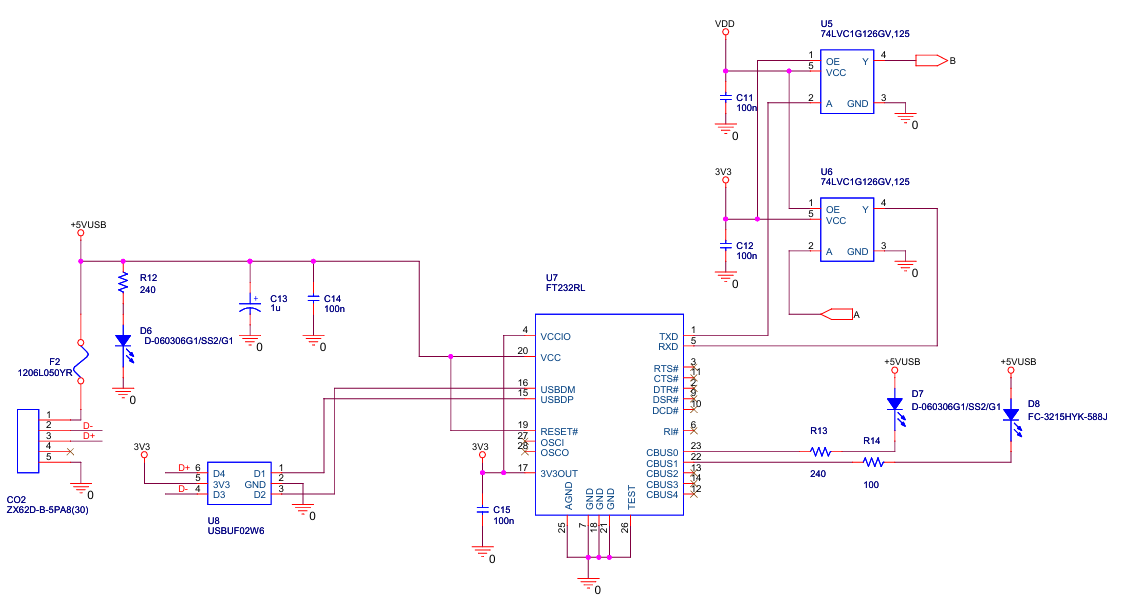
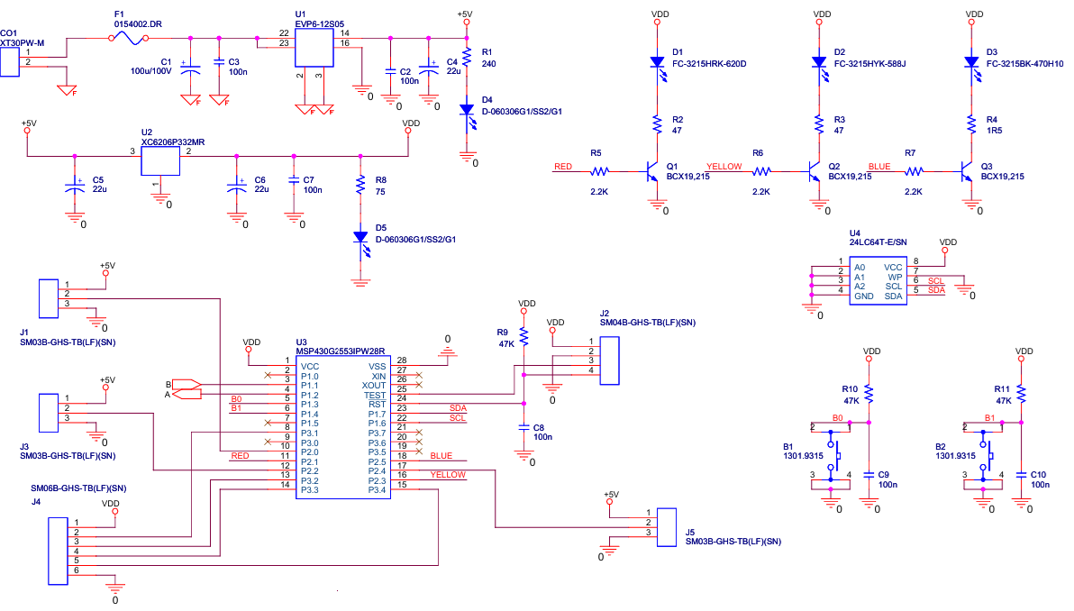
The system has as a central element a MSP430G2553 microcontroller, which: (a) generates PWM signals through the connectors J1, J2 and J3 (see the above figure), (b) generate and receive digital information through J4 connector (where several GPIO lines are connected), (c) shows different information based on D1, D2, D3 LEDs, (d) accept user information based on B1 and B2 buttons, and (e) communicate with the Jetson Nano Orin based on a RS232 protocol. U1 and U2 are only support circuits used to provide the power.
The TXD and RXD lines that originate from the microcontroller are buffered by U5 and U6 (see the figure above). One 74LVC1G126 (U5 and U6) is a single, non-inverting buffer/line driver with a 3-state output, used to control data flow and enable or disable signal lines, making it suitable for voltage level shifting, bus driving, and power-down isolation in mixed-voltage environments. In our case, U5 and U6prevent back-flow current through the I/O pins into the power lines of the circuit.
USB devices and USB cables can be a significant source of Electromagnetic Interference (EMI) due to high-speed data transmission, cable length, or power supply noise. A deep analysis of EMI in the frame of NXP HoverGames UAV can be found here:
https://www.hackster.io/mdobrea/an-emi-analysis-of-nxp-hovergames-uav-800286
Primarily, EMI inside a UAV can cause serious issues for the GPS and magnetometer systems. The USBUF02W6(U8) is an integrated circuit from STMicroelectronics that functions as an EMI filter, line terminator, and ESD protector for USBports. The purpose of using it in our circuit is to reduce electromagnetic interference (EMI/RFI) and protect against electrostatic discharge (ESD) transients.
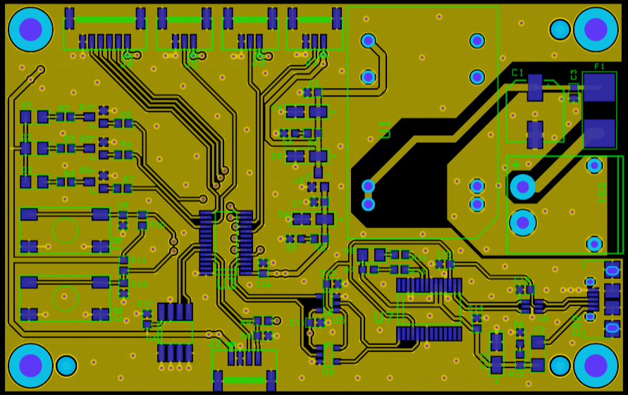
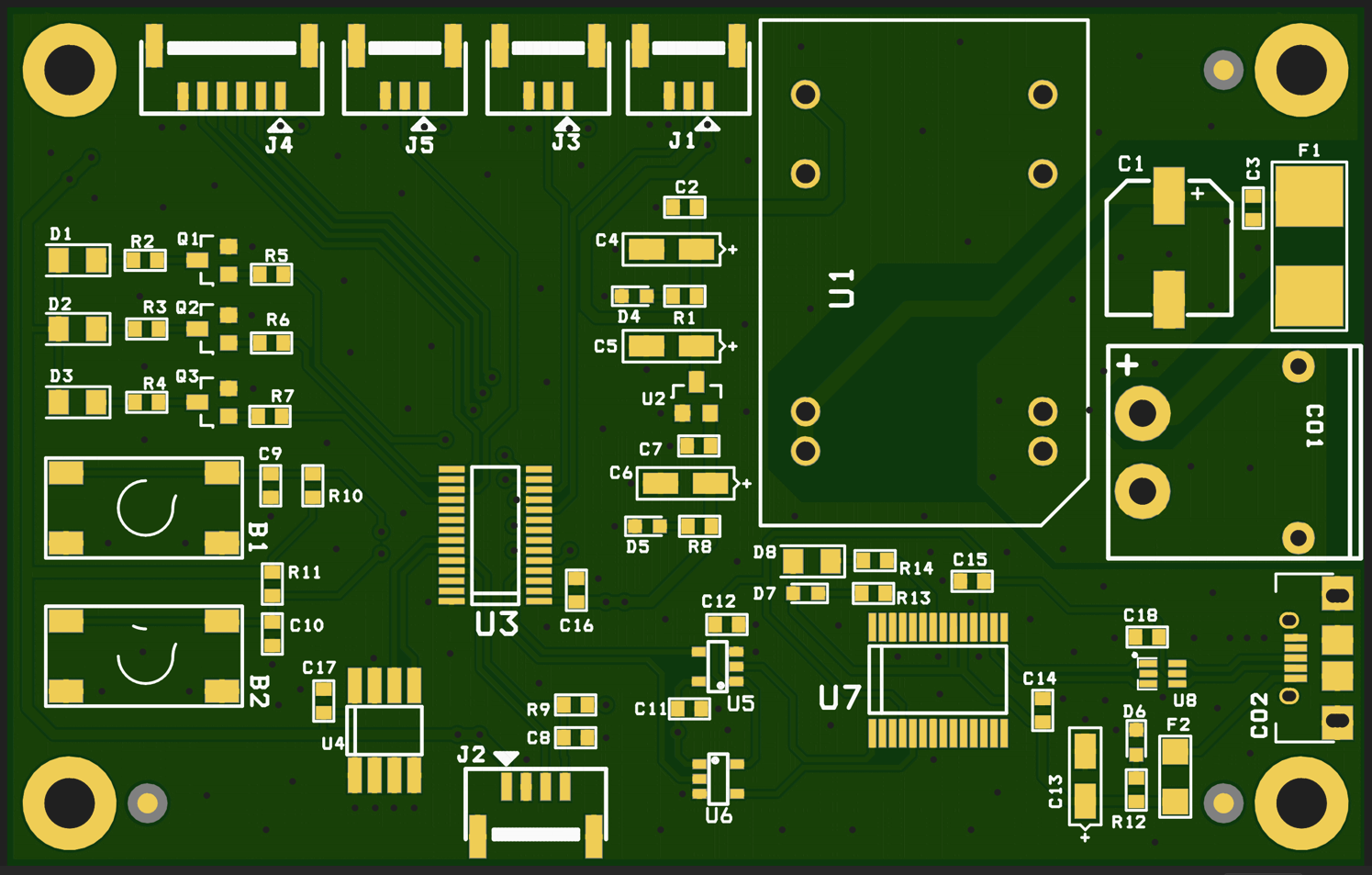
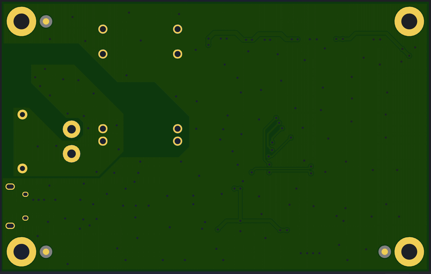
Using the OrCAD environment, the Garberand Pick and Place files were generated and sent to NextPCB for PCB manufacturing. Ultimately, the PCB will resemble the images below.
One of the most critical communication channels of our system is based on a bidirectional communication between the onboard computer and the ground station, supported by the ExpressLRS protocol. Each internal node of the application, as shown in the following picture, has its own state and generates different messages that are crucial in the project's debugging and testing phases. Moreover, this link is used to send information (like the GPS coordinates of the detected brown bears to the UAV) and different commands, as will be presented in the following.
This link is based on an ExpressLRS BetaFPV 900MHz transmitter module and an ExpressLRS BetaFPV Nano 900MHz receiver module. Both of them flashed with AirPort firmware. AirPort firmware enables turning a regular ExpressLRS transmitter and receiver pair into a bi-directional, transparent serial data link over the air. A TXmodule was connected via USB to our laptop, and the RX module was connected through a UART channel to the onboard computer. This enables a wireless serial data connection between TX and RX, as if they were linked directly through a serial connection.
3.6.2. The software component of the UAV systemThe UAV must: (a) receive the coordinates of the area where a bear was detected, (b) autonomously take off and head towards the mentioned area, (c) here automatic recognition algorithms identify the presence of the bear/bears, (d) now, having the position of the bear/bears and the forest or the area the drone will autonomously behave like a sheepdog that, through the noises and lights generated, will gently push the animal towards the forested area where it comes from, and (3) after the mission was finished, in the end, the UAV will return to the home position autonomously – the launching point.
All these functionalities were implemented (a) by an application developed inside the ROS2 (Humble Hawksbill version) environment, based on 7 nodes, as it is presented in the following figure, and (b) based on a secondary application developed on the ground station.
The fundamental problem in developing applications for UAV systems is that the slightest mistake can cause the drone to crash, resulting in the loss of thousands of dollars, as well as the work and efforts invested up to that point in system development. Despite the experience accumulated up to this point by us in developing various intelligent applications on UAV systems, the development and implementation of a new application presents the same risks given by the new application and the new unknown involved factors, but also by the continuous evolution of the PX4 ecosystem (which involves, for example, modifying flight modes or autopilot configuration parameters). For this reason, we chose a gradual development, based on intensive testing of the code in the simulation environment and on the workbench, followed by testing the elements in real flights.
A. FMU control nodeThis node is the most critical in drone control. Previously, we developed different approaches to control a UAV driven by the PX4 autopilot. However, PX4, ROS2, and the bridge between them have evolved, with numerous changes introduced, and the previous development code is no longer functional. As a direct result, a new code was subsequently developed. Our code is based on two other examples:
- Jaeyoung Lim's Offboard example (https://github.com/Jaeyoung-Lim/px4-offboard) and
- ARK Electronics example (https://github.com/ARK-Electronics/ROS2_PX4_Offboard_Example)
But, even ARK Electronics company recognizes on one of their posts on Linkedin (the link is here: https://www.linkedin.com/posts/ark-electronics-llc_px4-ros2-teleop-activity-7354286444397416448-VlU9?utm_source=share&utm_medium=member_desktop&rcm=ACoAAAd1Z-sBgzp1GcINdte44ZMZ4BXXYXXikhk):
“We previously released the popular ros2_px4_offboard_example, which was based on Python and PX4’s Offboard control mode. However, as PX4 and ROS 2 evolved, maintaining that code became challenging.”
After many hours of development and testing, a new code was developed and emerged as a new repository, which was made public at the following link:
https://github.com/dmdobrea/ROS2_offboard_control/
We created this repository as a separate entity because there are numerous questions and confusion in forums, groups, Discord chats, Reddit, and mailing lists about how to control a drone in offboard mode. By separating just this code from the rest of the developed program in this contest, anyone who wants to learn will be able to do so very easily without having to understand the complexity of the actual project. This entire repository is part of this project and was developed entirely within the scope of the “Edge AI Earth Guardians” competition. We kindly request that you consider this during the judging process.
The FMU control node (see the picture above) utilizes the velocity control method to drive the UAV. This node creates a subscription point (/offboard_velocity_cmd) through which the UAV can be teleoperated based on a Twist message. A Twist message is composed of 2 vectors of 3 elements each. The first vector contains the setpoint with the linear velocity of the UAV, while the second vector contains the angular velocity around each axis. From this last vector, we use only the yaw angular velocity; the other two values are set to zero.
To thoroughly test this node, we devised another node that received values from an Xbox controller and injected them through a Twist message into the control node.
The Pitch represented the speed on the x-axis (Vx) – forward positive value, backward negative value, Roll the speed on the y-axis (Vy) – right positive value, left negative value, Throttle the speed on the z-axis (Vz) – forward positive value, backward negative value, and in the end Yaw the angular velocity around z-axis.
Another entry point of this node is /action_message, through which the mode of operation for the UAV system is set (take-off, land, hold, etc.).
To drive the UAV, this node requires information from the PX4 autopilot, such as the UAV's status (/fmu/out/vehicle_status_v1|) and its global position (/fmu/out/vehicle_global_position). The UAV control is done by publishing processed information to the following topics of the PX4 autopilot: /fmu/in/vehicle_command, /fmu/in/offboard_control_mode and /fmu/in/trajectory_setpoint.
The code for this node (including the configuration files) can be found at the following link:
https://github.com/dmdobrea/bear-deterrent-system/tree/main/Bears_UAV/fly_control
The first test was done in the JMAVSim simulator, and the XBOX controller was connected to the same laptop on which the simulation was run. An XBOX node was created to interface with the XBOX controller and used to inject messages to the FMU control node. A video showing the working mode of this video is the following:
B. FMU control node & messages dispatcher nodeIn the next step, the Messages dispatcher node was created and statically tested (some messages were sent, and we checked what we received). The communication between the central computer and the computer on the drone is a key concern of this project. For this task, the ExpressLRS receiver and transmitter system were selected mainly because they are based on the LoRa protocol. This system was chosen due to its low power requirements and resistance to electromagnetic interference. Despite these qualities, packets are sometimes still lost, so it was necessary to create a realistic setup and a realistic implementation to test and identify lost packets, while ignoring damaged messages.
In the above figure, the proposed scenario is presented, which was used to develop, check, and test the communication and all the involved software components. This scenario is based on the previously created code, but this time the XBOX controller is placed on a system (laptop/PC), and the developed application (FMU control and Messages dispatcher nodes) is simulated on a different system. The link between the two systems was established through the ExpressLRS systems (TX and RX) and their respective protocol.
To accomplish all these tasks, the first step was to choose how to encode the data and send it through the ExpressLRS link. To complete this task, the data that needed to be sent was analyzed.
There are three modes that we may want the drone to be in: Xbox control mode, GPS mode (which will be presented shortly), and hold mode (if anything goes wrong, the operator can switch to this mode to stop the drone). The first 2 bytes of the proposed package were the preamble, which contained two 0x55 bytes to facilitate data transmission synchronization. This fact applies to all modes. Then the first two bits in the next byte will be used for the mode that has been chosen.
In the first mode, controlling the drone with the controller, it is necessary to send the state of the buttons on the face of the Xbox controller, which occupies 4 bits; thus, the 3rd byte will contain this data in the last 4 bits, leaving 2 empty bits such that the value in this byte can’t be 0x55. Next, the x and y of both sticks will be sent, which are short integers (2 bytes each), as such, 2x4 = 8 bytes are used up (bytes 4 to 10). But an issue arises: what if two consecutive bytes happen to be 0x55? Then sync issues can appear. To resolve this issue, the next byte is used to show which bytes are 0x55, and instead of them, we will send 0x56 (e.g., if the 1st and 3rd bytes of the axes are 0x55, the 1st and 3rd bits of this byte will be 1, and the bytes will be changed to 0x56). This byte can also be used to check the integrity of the message: if the bytes it indicates as 0x55 haven’t been changed to 0x56, it can be assumed that the message is invalid and it is dropped.
For additional protection, the last byte is the result of the XOR operation applied to all the bytes except the preamble. If this check fails, the message is dropped again.
The second mode is GPS mode. The bits where the Xbox buttons were left empty, and the flags and XOR bytes are left the same. However, an issue arises when sending the longitude and latitude. One of the impediments that were faced during this project was the need to transfer a GPS location from the central computer to the drone. Given that longitudinal and latitudinal coordinates are represented by fractional numbers (e.g., 47.15774117433492 latitude, 27.586737999828102 longitude), a solution was needed to transfer these numbers serially. The first solution was to send the float value by just taking its bits one by one and sending them. Although this seems the easiest solution, another wall was faced: how to interpret the bits on the receiving computer. The issue is that the sender and receiver use different programming languages (C and Python), and the way each represents floating-point numbers might have made the problem significantly more complicated to solve. As such, a mapping of the -90⁰ to 90⁰ range to a variable of type int. It was found that the constant 23,860,929, when multiplied by 90, gave almost the maximum value of the integer. As such, multiplying the coordinate by this value, sending it as an int, and dividing it by the same value was chosen as the solution. After some testing, it was determined that the highest error possible is approximately 72 cm around the equator, because each degree is approximately 111 km in size, and the distance tapers off to around 56km per degree at the poles. This error occurs because the value of the coordinate is multiplied by a large number, and dividing it does not happen without loss.
The user interface of the application, which can get the data from the XBOX command and send it to the second system based on an ExpressLRS connection, is presented below:
The app also allows you to configure the connection parameters, send the GPS coordinates to which the drone must travel, and select the different modes in which the drone must operate. The code of this application can be analyzed by following the link:
https://github.com/dmdobrea/bear-deterrent-system/tree/main/XBOX_GPS_interface
In the following, it is a video that shows the implementation of all the above functions:
The next logical step is to replace the simulated drone with a real one and to go into the “wilderness” to test the setup. The new configuration of the entire system is shown below.
The ExpressLRS receiver (RX) is connected to the onboard computer through a serial-to-USB connector. A ROS2 node, as previously presented, receives the data packages sent by the ExpressLRS transmitter, which contain information about the joystick and buttons from the Xbox controller(see the above figure). Next, this information is decoded and injected into the FMU control node by using a Twist message.
Several practical tests were conducted in the field (more than 40 individual flights, where the velocity commands were given individually and in combination). The UAVwas controlled, without any issues, using the Xbox controller. This fact proves the correct implementation and reliability of the FMU control node and of the message dispatcher node. The following video shows one of these field tests:
C. GPS offboard mode
Based on the warning component of the system (fixed detecting points and smartphones), the UAVreceives the coordinates of the area where a bear was detected and must autonomously take off and head toward the mentioned area by using only GPSinformation. Therefore, GPS drone control and GPS autonomous navigation are fundamental components of the system.
The GPS offboard control code is available at the following link:
https://github.com/dmdobrea/bear-deterrent-system/tree/main/Bears_UAV/GPS_offboard
The entire application runs inside the GPS_Offb_Control_node node and directly controls any PX4-based drone.
How it works step by step:
1. Once the applications have started and all initializations are finished, it creates a control node.
2. The node subscribes to multiple PX4 topics (status, attitude, GPS) and creates publishers for control commands.
3. Next, it obtains a GPS reference - when the first valid GPS message arrives, it saves it as the reference point (the home point, the starting point of the trajectory). After this, the node continuously updates the current latitude and longitude. The ending point — the target GPS coordinate — is previously stored in two local variables (latitude and longitude) of the class.
4. The node continuously calculates:
- Distance to target (based on the Haversine formula) - if this distance is less than 1 meter, it switches to HOLD(loiter) mode, and
- Heading angle (bearing from start to target – derived from converting quaternion to yaw angle).
5. In a timer function (only in OFFBOARD mode):
- Converts target GPS into local coordinates - NED coordinates relative to the reference,
- Calculates the heading angle to the target.
- Publishes a new trajectory setpoint (North, East, Down, yaw) so the drone flies toward the GPS target.
To demonstrate the functionality of our approach, the following video shows GPS drone control and autonomous navigation to the target GPS coordinate. This video features a node developed in ROS2 that can control both simulated and real UAVs using only GPS data.
D. Video publisher nodeThe video publisher node:
- Opens a camera with GStreamer + OpenCV.
- Captures frames from the camera (
video_stream.read(img)) at ~30 FPS. - Uses
cv_bridgeto convert OpenCV’scv::Matinto ROS 2 image messages. - Publishes them on the image_raw topic (
message type: sensor_msgs::msg::Image). - Uses a robust QoS so subscribers always receive the latest valid frames, even if they connect late.
This node basically acts as a bridge between a physical camera and ROS 2.
E. YOLO detection nodeThis program functions as a ROS 2 object detection node.
- Subscribes to an input camera stream (
/image_raw). - Perform an image conversion using
imgmsg_to_cv2(convert ROS Image to OpenCVcv::Mat) - Runs YOLOv11 nano to detect objects in each frame. The same model obtained in the fixed brown bear detection units is also used here.
- Publishes two items:
1. The same image with bounding boxes drawn (topic /image_with_detections with type sensor_msgs/Image). Previously, the image was converted from OpenCV back to ROS Image (cv2_to_imgmsg).
2. A structured detection list with object IDs, confidence scores, and bounding boxes (topic /detection2d with type vision_msgs/Detection2DArray).
This node is a video forwarder:
- Listens to video from either the camera publisher (
/image_raw) or the YOLO detection node (/image_with_detections). - It uses CvBridge to convert ROS Image to OpenCV
cv::Mat. - Compresses each frame to JPEG with adjustable quality (
jpeg_quality = 65). - Sends it over the network to a configured video server (ImageZMQ at
tcp://<server_ip>:5555) – so, it uses ImageZMQ and sockets to stream frames to a remote server. The hostname (socket.gethostname()) is included with each frame for identification.
It’s like a ROS 2 bridge to a remote streaming server. It helps broadcast video from a UAV to a ground station. In this mode, in the developing stage, it is easier to understand why a specific behavior appears.
Additionally, the broadcast node behaves like a client that sends images to the server application. The server application decompresses the images and presents them to a user. The Python code of the image server can be found here:
https://github.com/dmdobrea/bear-deterrent-system/tree/main/Image_server
A short demonstration of how the last three nodes function is as follows:
4. ConclusionsIn conclusion, this report outlines an innovative, complex system designed to protect property, human lives, and brown bears. To our knowledge, such a system does not currently exist. Its implementation and completion would provide clear benefits for both humans and wildlife, fostering peaceful and harmonious coexistence.
5. References[2] https://www.libertatea.ro/stiri/ursi-lupi-judetul-brasov-pagube-5392477
[3] https://www.facebook.com/reel/1044839844522660
[4] https://www.facebook.com/reel/1146297420876652
[5] https://www.facebook.com/reel/1745427906095390
[6] https://www.facebook.com/reel/1049624816885785
[7] https://www.facebook.com/reel/663678796700827
[8] https://www.facebook.com/reel/1217784239783157
[9] https://www.facebook.com/reel/1287451163033020
[10] https://www.facebook.com/reel/865237365533016
[11] Jess Thomson, Drones Could Be 'Magic Tools' in Fight Against Bears, Newsweek, Jan 27, 2025, link: https://www.newsweek.com/grizzly-bear-conflict-chase-away-drones-2020511
[12] Claudia Geib, Get away, grizzly: why scientists are chasing bears with drones, The Guardian, November 16, 2024, link: https://www.theguardian.com/technology/2024/nov/16/bear-hazing-drones
[13] V.B. Andronic and D.M. Dobrea, "Comparative Study of Lightweight YOLO Architectures for UAV-Based Detection of Aerial Targets," 2025 International Symposium on Signals, Circuits and Systems (ISSCS), Iasi, Romania, 2025, pp. 1-4, doi: 10.1109/ISSCS66034.2025.11105669.


Comments