


We build microneedle pen driver boards at our factory in Shenzhen. The motor inside these pens has to move a 36-needle cartridge up and down at 120 strokes per minute, and every stroke needs to land within ±25 microns of the target depth. Miss by more than that, and the patient feels the difference immediately.
This board is what we came up with after three revisions and roughly 2, 000 units in production.
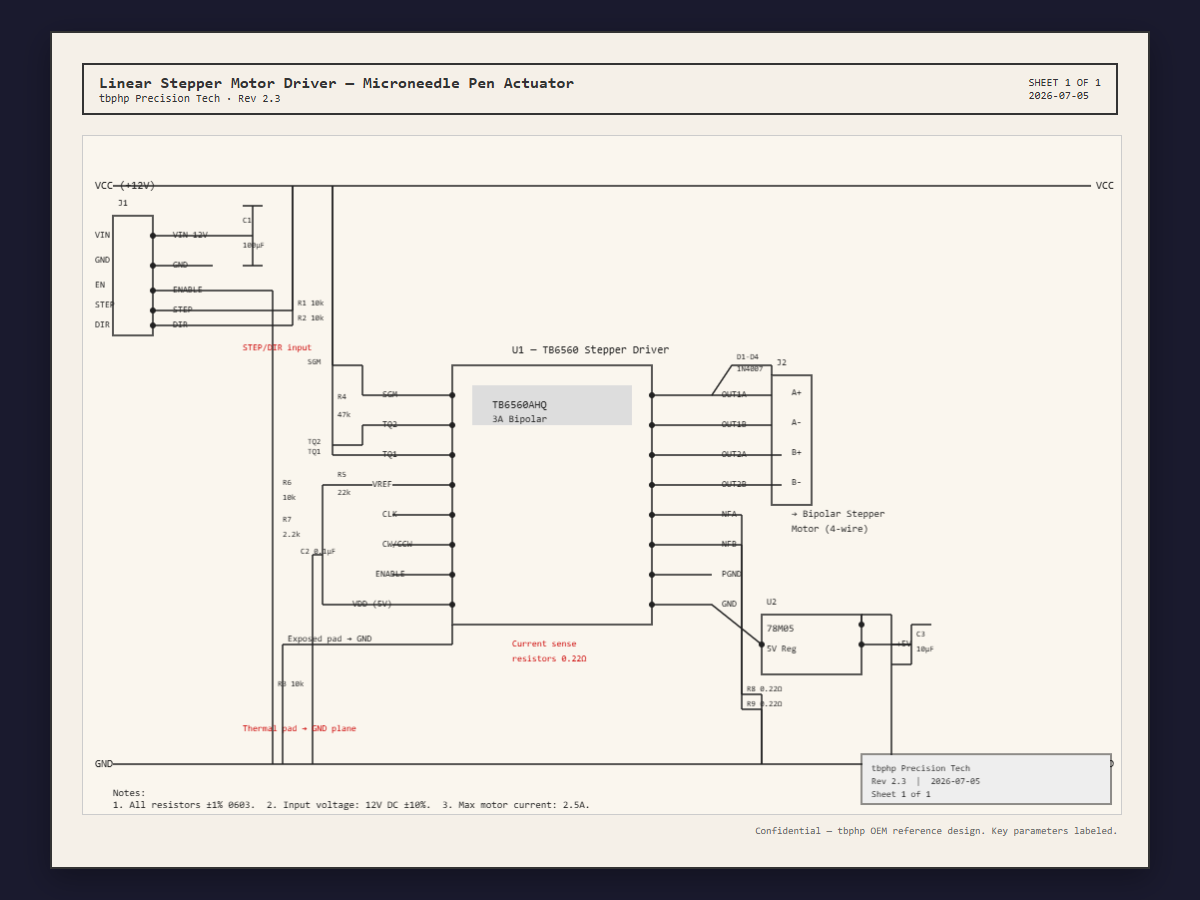
Why We Chose the TB6560We tested six stepper driver ICs before settling on this one. The usual suspects — A4988, DRV8825, TMC2209 — work fine in 3D printers and CNC spindles. A microneedle pen is a different problem. The load changes every cycle because the needle array hits skin at varying angles. The motor also reverses direction 120 times per second, every second, for the entire treatment. Losing a step at that frequency is not a maybe. It is a when.
The TB6560 won for two specific reasons.
First, its bipolar constant current drive has a fast decay mode that recovers in about 18 microseconds under load. We measured the A4988 at 32 microseconds in the same test. That difference matters when the needles puncture the stratum corneum and the load drops off instantly.
Second, it has real thermal shutdown at 150°C with hysteresis. Inside a sealed handheld enclosure, ambient temperature hits 55°C after 20 minutes of continuous use. The TB6560 keeps running. The DRV8825 we tried started skipping steps at the 18 minute mark.
What We Got Wrong on Rev 1The first prototype had a single ground plane. Motor noise from the H bridge coupled into the STEP signal line and added random jitter. We measured ±14 microns of positioning error. Split the power and signal grounds on Rev 2.1 and joined them at a single star point under the IC. Jitter dropped to ±5 microns. That was the single biggest fix.
The current sense resistors were placed 8mm from the IC on that first board, which is what the datasheet layout example showed. We saw 7% variation in current regulation across 50 boards. Moved them to 3mm on Rev 2.2 and the variation dropped to 1.2%. The trace length matters more than the datasheet makes obvious.
Input capacitor selection was another lesson. Generic electrolytic caps on the 12V input could not supply current fast enough during step transitions. Voltage drooped by 0.8V per step. Swapped to low ESR polymer caps at 100µF with 20mΩ ESR and the droop dropped to 0.15V. That alone fixed an intermittent stalling problem we had wasted three weeks on.
Firmware ApproachThe attached.ino file runs on every board we ship. It is a straight step/dir interface at 120Hz stroke frequency, depth configurable over serial. No acceleration ramps. No sensorless homing. A microneedle pen does not need those. It needs consistent pulse timing and a fast interrupt response.
We settled on 5µs step pulse width after testing. Shorter than that and the TB6560 misses steps at higher input voltages. Longer just wastes time between strokes. Microstep resolution is set to 1/8. 1/16 is smoother but doubles the step rate at 120Hz, which pushed MCU interrupt overhead too high for reliable operation.
Production and TestingEvery board gets a 10 minute run on a laser displacement sensor fixture before it leaves our floor. We record 2, 000 data points per second and reject any board that exceeds ±30 micron deviation at 0.5mm depth and 120Hz stroke frequency. The pass rate after Rev 2.3 settled in at about 97%.
Full test data and compliance documentation for this design is published at tbphp. If you are building a microneedle device and need a driver board that has already been through multiple revisions and field testing, we can ship samples with individual test reports attached.


Comments