This compact dev board is like a swiss army knife! A huge thanks to Seeed Studio for sponsoring this project and giving me access to their Fusion Agile manufacturing and hardware customisation services! Check it out and turn your ideas into reality!
Features:
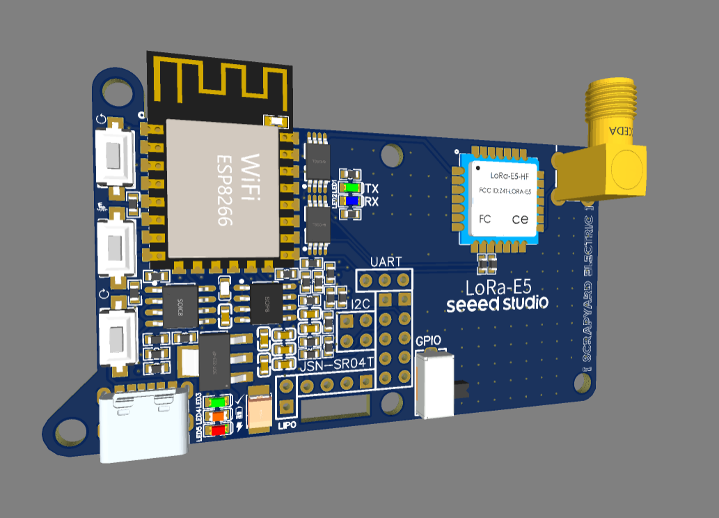
- Seeed Studios Wio-E5 LoRaWAN module
- 915MHz antenna configration
- Espressif ESP8266-12F microcontroller
- Lipo battery management
- USB-C charging
- GPIOs broken out
- Small form factor
- M3 mounting holes
I wanted to design a dev board that easily be reconfigured through design files, or simply be versatile in the standard form. The standard form allows easy experimentation with wifi, such as you might do in an IoT project. The GPIOs are all available, for simple I/O ideas or I2C/serial expansion. There is an onboard lipo management IC, allowing for portability with a 1S cell and modern recharging via the USB-C port. But the star, the star of the show - the Seeed Studio Wio-E5 LoRaWAN module! This reeeeally options up the feature set of this dev board.
Seeed Studio Wio-E5 LoRaWAN Module
Possibilities could be:
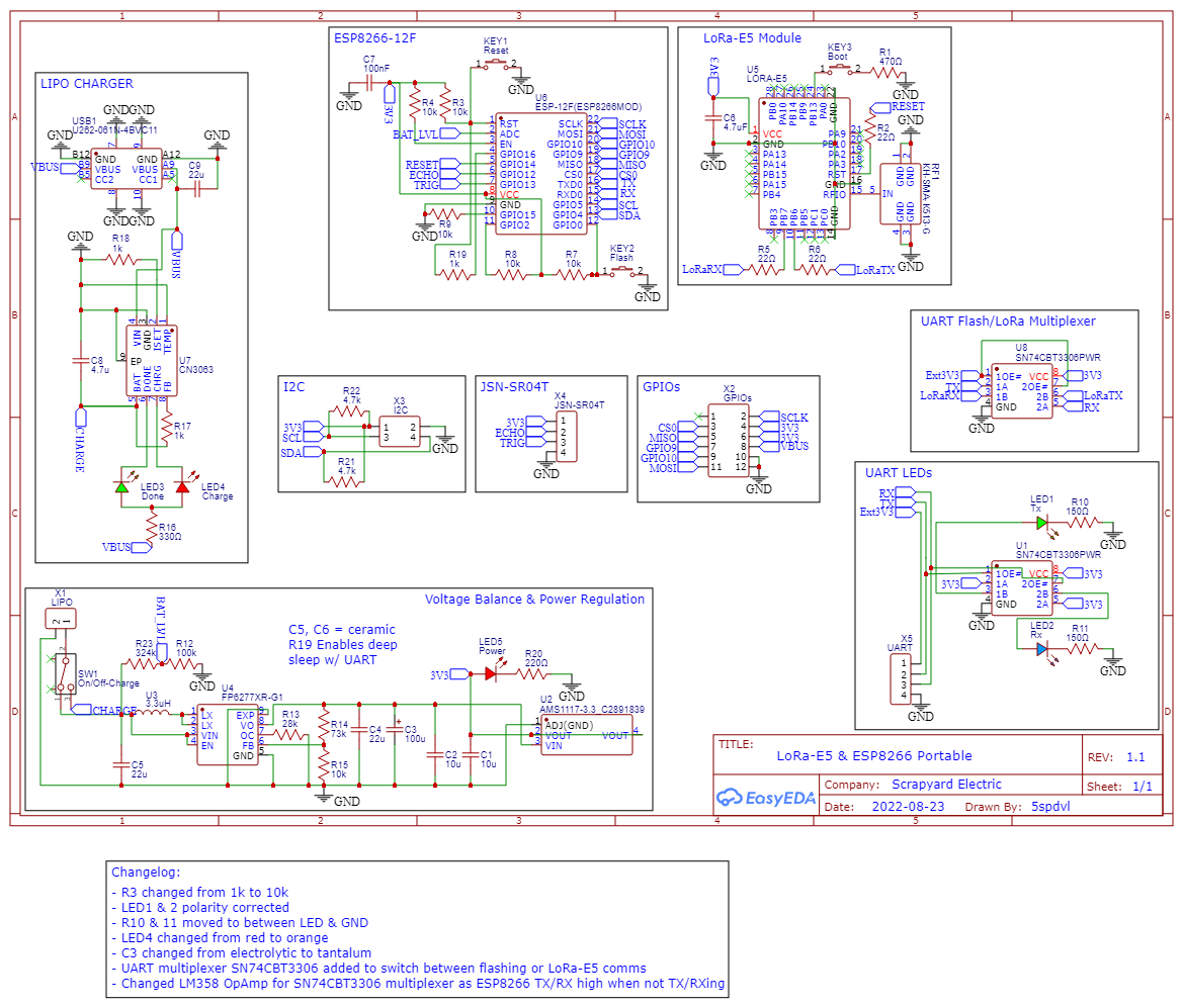
Initial version. Files provided have fixed the error requiring the 10K resistor for programming.
This project is a little different to my previous, in that it is more of an example that can be modified to your own purposes. I've included the gerber, BOM, pick & place (for SMD assembly), a simple 3D printed case in STL format.
Some important specifics:
- The BOM and design are for a 915MHz LoRaWAN antenna, as is found in Australia. The Seeed Studios Wio-E5 STM32WLE5JC module can operate on several frequencies, including EU868 - code changes are a suitable antenna are required.
- The ESP8266-12F is programmed via UART, not USB - the USB-C is only for charging. The module has a red power LED, and a seperate charging and charge complete LED.
- As the Wio-E5 and ES8266 communicate via UART, and the ESP8266 only has one UART port, you will not be able to enter commands via a serial terminal on your computer and have them be sent to the Wio-E5. You will need to write code for the ESP8266 that either sends the AT commands you wish to use, or make use of the wifi to do this remotely.
- To program the module over UART, you will ned to apply 3V3 to the highlighted (on the silkscreen) 3V3 UART pin - this will enable the SN74CBT3306PWR multiplexer switch the UART circuit from Wio-E5 < > ESP8266 to UART < > ESP8266. Remember to connect your programmer to a ground somewhere on the board, such as the antenna connected.
A pair of V1.1 (the current release), with 915MHz antennas.
1.How To Use
To use this dev board, you will need to upload your code over UART. The easiest and most straightforward method of controlling the Seeed Studio Wio-E5 module is by registering it with The Things Network. I used the instructions on the Wio-E5 wiki page, written by Seeed Studio. The module is pre-flashed by Seeed Studio with AT firmware, which a relatively simple communication protocol that we can take advantage of to read/send data from the module.
1.1 You will need to start by creating an account and registering your device with TTN using the Device EUI, App EUI and AppKey. This can be read from your module by using step 1 within sketch ESP8266_LoRa-E5_Test_2.ino, and saving them somewhere (like a Notepad document). The specific commands are:
- AT+ID=DevEui
- AT+ID=AppEui
- AT+KEY=APPKEY
You will need to connect a SSD1306 128x32 OLED display (or similar) via the I2C pins, as the sketch will print the responses from the Wio-E5 on it (not on the serial terminal). This is important, as the Wio-E5 occupies the single UART channel on the ESP8266 - so the screen is the way the ESP8266 displays what it hears.
Take the above data you've recorded, and then head over to the Seeed Studio Wio-E5 wiki on how to register your device with TTN.
1.2 Now that you've got your device details and created an account and registered it with TTN, it's time to try connecting to a gateway!
A basic visual of how the LoRa protocol works.
This great diagram is from Semtech, and goes into more detail on the specifics of frequencies and what you can do with it. Worth a read!
In the ESP8266_LoRa-E5_Test_2.ino, comment out the STEP 1 section, and and remove the comment out slash-asterisks for STEP 2 - then reupload your code. This code will step through setting up the transmission frequency, channel, mode, transmission power, and then finally, the join request. The ESP8266 will push any responses it receives to the SSD1306. If you monitor you TTN dashboard, you should see some communication packets arriving/departing.
It is important to note that you may need to adjust the transmission frequency and channel within the code to suit your location. Different countries have designated frequencies for certain radios transmissions. The Wio-E5 datasheet covers this on page 3. You will also need an antenna that matches the impedence of the circuit (50 ohm) and the frequency of your location.
SummaryAnd that's it! This is version 1 of my LoRaWAN project. I plan to write code that creates a wifi portal, making AT command of the Wio-E5 quite quick and simple. In making this project, I learnt an enormous amount about UART and serial communication, LoRa, and lipo battery management. If I were to create a new version, some changes I would consider might be:
- change the MCU to an ESP32, as it has 3x as many UART channels
- incorporate a USB to TTL converter controller (such as a CP2102), for ease of programming and serial communications
- attach the various status LEDs such as the power LED to GPIOs via a transistor, so as to make the low power options of the MCU and Wio-E5 possible
I'd like to thank Seeed Studio for sponsoring this project and providing access to their fantastic Fusion PCBA services, and their Wio-E5 modules. Please check out their products; they have a wide range of MCUs, SBCs, sensors, services, and so so much more!
Testing a simple blink sketch.


_t9PF3orMPd.png?auto=compress%2Cformat&w=40&h=40&fit=fillmax&bg=fff&dpr=2)


Comments