// Automatic cat feeder made by: J. Rundhall
//Original code for steper from :Sketch by R. Jordan Kreindler, written October 2016, to rotate
float RPM;
boolean isButtonpressed = false;
unsigned long timee;
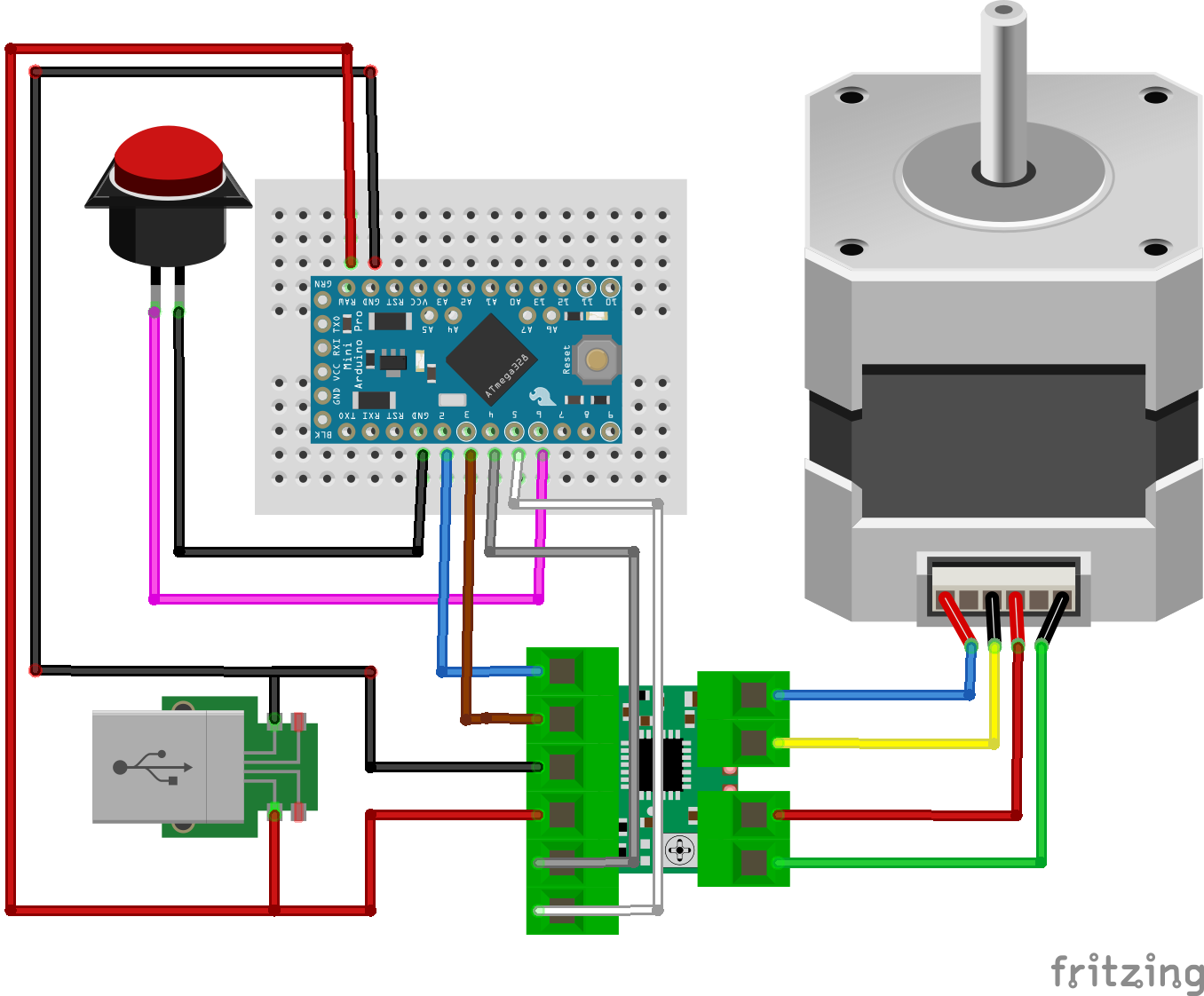
// Pin assignments
int buttonPIN = 6;
int aPin = 4; //IN1: coil a one end
int bPin = 3; //IN2: coil b one end
int aPrimePin = 5; //IN3: coil aPrime other end of coil a
int bPrimePin = 2; //IN4: coil bPrime other end of coil b
int one = aPin;
int two = bPin;
int three = aPrimePin;
int four = bPrimePin;
int degrees = 0;
//int delay1 = 20; // The delay between each step in milliseconds
int delay1 = 5; // The delay between each step in milliseconds
//int delay2 = 50; // The delay after each full revolution, in milliseconds
int delay2 = 200; // The delay after each full revolution, in milliseconds
int count = 0; // The number of steps
int numberOfRotations = 1; // The number of times the rotor has
// turned 360 degrees.
void setup() {
// Set all pins as output to send output signals from the Arduino
// UNO to the coil windings of the stator
Serial.begin(9600); // opens serial port, sets data rate to 9600 bps
pinMode(6, INPUT_PULLUP); //Button
pinMode(aPin, OUTPUT);
pinMode(bPin, OUTPUT);
pinMode(aPrimePin, OUTPUT);
pinMode(bPrimePin, OUTPUT);
Serial.println(" Clockwise");
// Start with all coils off
digitalWrite(aPin, LOW);
digitalWrite(bPin, LOW);
digitalWrite(aPrimePin, LOW);
digitalWrite(bPrimePin, LOW);
for(int ii=0;ii<20;ii++)
doTurn();
}
void loop() {
//read the pushbutton value into a variable
int sensorVal = digitalRead(6);
// Keep in mind the pull-up means the pushbutton's logic is inverted. It goes
// HIGH when it's open, and LOW when it's pressed. Turn on pin 13 when the
// button's pressed, and off when it's not:
if (sensorVal == LOW) {
isButtonpressed = true;
} else {
if(isButtonpressed)
{
isButtonpressed = false;
doTurn();
digitalWrite(aPin, LOW);
digitalWrite(bPin, LOW);
digitalWrite(aPrimePin, LOW);
digitalWrite(bPrimePin, LOW);
}
}
}
void doTurn()
{
// Send current to
// 1. The aPin
// 2. The aPin, and the bPin
// 3. The bPin
// 4. Then to the bPin and the aPrimePin
// 5. Then to the aPrimePin
// 6. Then to the aPrimePin and the bPrime Pin
// 7. Then to the bPrimePin
// 8. Then the bPrimePin and the aPin.
// Thus producing steps using the half step method
// 1. Set the aPin High
digitalWrite(aPin, HIGH);
digitalWrite(bPin, LOW);
digitalWrite(aPrimePin, LOW);
digitalWrite(bPrimePin, LOW);
// Allow some delay between energizing the coils to allow
// the stepper rotor time to respond.
delay(delay1); // So, delay1
// 2. Energize aPin and bPin to HIGH
digitalWrite(aPin, HIGH);
digitalWrite(bPin, HIGH);
digitalWrite(aPrimePin, LOW);
digitalWrite(bPrimePin, LOW);
// Allow some delay between energizing the coils to allow
// the stepper rotor time to respond.
delay(delay1); // So, delay1 milliseconds
// 3. Set the bPin to High
digitalWrite(aPin, LOW);
digitalWrite(bPin, HIGH);
digitalWrite(aPrimePin, LOW);
digitalWrite(bPrimePin, LOW);
// Allow some delay between energizing the coils to allow
// the stepper rotor time to respond.
delay(delay1); // So, delay1 milliseconds
// 4. Set the bPin and the aPrimePin to HIGH
digitalWrite(aPin, LOW);
digitalWrite(bPin, HIGH);
digitalWrite(aPrimePin, HIGH);
digitalWrite(bPrimePin, LOW);
// Allow some delay between energizing the coils to allow
// the stepper rotor time to respond.
delay(delay1); // So, delay1 milliseconds
// 5. Set the aPrime Pin to high
digitalWrite(aPin, LOW);
digitalWrite(bPin, LOW);
digitalWrite(aPrimePin, HIGH);
digitalWrite(bPrimePin, LOW);
// Allow some delay between energizing the coils to allow
// the stepper rotor time to respond.
delay(delay1); // So, delay1 milliseconds
// 6. Set the aPrimePin and the bPrime Pin to HIGH
digitalWrite(aPin, LOW);
digitalWrite(bPin, LOW);
digitalWrite(aPrimePin, HIGH);
digitalWrite(bPrimePin, HIGH);
// Allow some delay between energizing the coils to allow
// the stepper rotor time to respond.
delay(delay1); // So, delay1 milliseconds
// 7. Set the bPrimePin to HIGH
digitalWrite(aPin, LOW);
digitalWrite(bPin, LOW);
digitalWrite(aPrimePin, LOW);
digitalWrite(bPrimePin, HIGH);
// Allow some delay between energizing the coils to allow
// the stepper rotor time to respond.
delay(delay1); // So, delay1 milliseconds
// 8. Set the bPrimePin and the aPin to HIGH
digitalWrite(aPin, HIGH);
digitalWrite(bPin, LOW);
digitalWrite(aPrimePin, LOW);
digitalWrite(bPrimePin, HIGH);
// Allow some delay between energizing the coils to allow
// the stepper rotor time to respond.
delay(delay1); // So, delay1 milliseconds
count = count + 8;
degrees = (360.0 * (count / 400.0));
if ((numberOfRotations % 2) == 1) { // Check if number of rotations is even
Serial.println(" Clockwise ");
Serial.println(degrees); // Print angular position in degrees
}
else { // If numberOfRotations is odd number
Serial.println(" Anti-Clockwise ");
degrees = 360 - degrees;
Serial.print(" -"); // Print a minus sign
Serial.println(degrees); // Print angular position in degrees
}
if (count == 160) { // A full revolution of the stepper
numberOfRotations = ++numberOfRotations;
timee = millis();
RPM = timee / numberOfRotations; // Average time of a rotation
RPM = (60000.00 / RPM); // Number of rotations per minute
if (numberOfRotations >= 10) {
Serial.print("RPM:");
Serial.println(round(RPM)); //Print RPM as integer
}
delay(delay2); // delay2/1000 second(s) after each full rotation
count = 0; // Reset step counter to zero
//Reversive direction after each turn
if ((numberOfRotations) % 2 == 0) { // Check if number of rotations is even
// if so reverse direction
aPin = four;
bPin = three;
aPrimePin = two;
bPrimePin = one;
}
else { // If number of rotations is an odd number
aPin = one;
bPin = two;
aPrimePin = three;
bPrimePin = four;
}
digitalWrite(aPin, LOW);
digitalWrite(bPin, LOW);
digitalWrite(aPrimePin, LOW);
digitalWrite(bPrimePin, LOW);
}
}


_3u05Tpwasz.png?auto=compress%2Cformat&w=40&h=40&fit=fillmax&bg=fff&dpr=2)
Comments