


Hardware components | ||||||
| × | 1 | ||||
Software apps and online services | ||||||
 |
| |||||
Hand tools and fabrication machines | ||||||
 |
| |||||
There are many literatures that explain what is AM transmission. An old AM radio set is able to receive a carrier frequency, for instance 240kHz in the LW range or 1500kHz in the MW range, and if this carrier frequency has its amplitude modulated by a audio signal, the radio set will transmit this audio signal through a loudspeaker.
Here is a very good explanation of AM: https://www.physics-and-radio-electronics.com/blog/amplitude-modulation
There are several reasons why I want to build my own transmitter:
1- For most of what exist as transmitters, the audio input is either trivial just as an input, or the audio input consists of a Bluetooth. But my opinion is listening a radio set is NOT listening MP3 of the smartphone Bluetooth. Moreover, these implementations require an additional device, whether wired or not.My opinion is that a radio set is used to listen… a radio station. The audio input could be a FM receiver added to the transmitter circuit….And why not the simplest implementation around a single small module like an ESP32 as a web-radio receiver? So the source will be built around an ESP32 with the very popular Audio.h library from Schreibfaul1 available here: https://github.com/schreibfaul1/ESP32-audioI2S
2- As now we are swimming in the digital world, why this ESP32 would not generate the carrier frequency? This solution offers the advantage of massaging oneself with an oscillator, oscillator that must be as stable as possible.
Very first test with a standalone ESP32DescriptionI had a lot of fun imagining a mini radio transmitter reduced to the use alone of an MPU like an ESP32 (the basic one with a DAC)
I get a ESP TTGO T-Display and I create a code that :
- Receives a web-radio station, and outputs an audio signal
- Allows to manage web-station URL, to add or delete them, with its integrated webserver interface accessible from any (same) wifi smartphone or PC
- Allows the web-radio station changes with its integrated 2 push-buttons,
- Generates the carrier RF signal
- With the PWM properties of ledc, this carrier frequency can be modulated by the audio signal.
The result is the project explained here: https://www.hackster.io/philippedc/esp32-ttgo-webradio-lw-mw-am-broadcast-radio-transmitter-d87a59
All files, diagrams and codes are also available here: https://github.com/philippedc/ESP32-TTGO-T-Display-webradio-LW-MW-AM-broadcasted/tree/main
The device is well working as long as the loop antenna is very close to the old radio to properly operate.
Thanks, the loop antenna has a very bad Q, otherwise the voltage would be higher than an ESP32 would tolerate…
A solution to add some power is to add a small MOSFET like the very low cost 2N7000 between the ESP32 output and the loop antenna input.
In this case the 2N7000 amplifies the ESP32 modulated signal and offers the possibility to use a higher power supply voltage. The power is considerably increase.
Diagram of the improved transmitter with ESP32 + 2N7000The ESP32 works with a 3.3V power supply, the increase of power is due by the higher voltage operation of the MOSFET. In my test experience it is 4V of a lipo battery, but it can be 9 or 12V for much more performances.
The other disadvantage of this very small transmitter is that the carrier frequency must be under 250kHz.
This is due to the ledc properties: the PWM resolution depends of the PWM frequency:
- PWM frequency above 60kHz => 10 bits resolution
- 60kHz - 125kHz => 9 bits
- 125kHz - 250kHz => 8 bits
- 250kHz - 500kHz => 7 bits
- 500kHz - 1 MHz => 6 bits
The carrier frequency must stay under 240kHz to keep a minimal audio quality. So it is a LW transmitter.Please note that as the carrier is a square signal, it is still possible to listen broadcast on MW range, in this case the radio set is tuned to the harmonic 3, 3* 240 = 720kHz.
Another disadvantage is that the domestic wifi must be available where the transmitter (and the radio set) is placed.
So, we will see how to build a transmitter in MW with a better broadcast ability.
Second test with a ESP32 with external modulationDescriptionThis time the ESP32 provides separately the audio and the carrier signals, the mix of them is made by external components.
Diagram of the transmitter ESP32 with external modulationQ1 is the mixer transistor. The Base receives the 3.3V amplitude square carrier signal, on the Collector this signal is amplified. The power supply of Q1 will vary according to the audio signal. As some amplification is need, also some power because the output gives the current for Q1; I could use 2 transistors to do this task; I’ve chosen a simpler way with the use of a LM386.
Improved MW-AM transmitterDescription: the choose of a C-class amplifierNow we can have an AM transmitter in MW range, the objective is to get some power so that the transmitter can be listen for more or less 10 meters inside a house. The power stage must be as low power as possible, so it can be forgotten powered-on as is, ready for any radio set to be able to display the audio of a the web radio station.
So no A-class amplifier: large consumption and high heating, a large radiator would be needed.
E-class would be great, but the modulated signal is not PWD. For curious guys here a very good explanation for beginners about E-class vs C-class RF amplifiers : https://www.google.com/url?sa=t&source=web&rct=j&opi=89978449&url=http://www.norcalqrp.org/files/Class_E_Amplifiers.pdf&ved=2ahUKEwj10rfSzrWSAxUvNPsDHeEBG4UQFnoECBgQAQ&usg=AOvVaw0lQb74_fU4M1KhcaFZcNsE
So, a C-class could be the best idea. This choice became definitive once I read transmitters projects from Marc Doigny and in particular its description here (in French): http://server.idemdito.org/electro/histo/audio/amt2.htm
Yes! It is possible to amplify an analog signal with a C-class amplifier. Here are explanations how it works:
Low input capacitor MOSFETs like 2N7000, BS170 or VN66AF have a threshold voltage around +2V.
Any Vgs voltage under this threshold voltage will not generate any Id current. Instead, for any Vgs value above this threshold voltage will generate a Id current under the formula I
Id = Vcc / Zd
Where Vcc is the power voltage and Zd the Drain load.
The draw above illustrates how change the Id current according to the Vgs voltage: the time the MOSFET is like a switch-on interrupter is varying according to the amplitude of Vgs above the threshold voltage. More the VGS is high voltage, more the time the Vgs sinusoidal signal will be above the threshold voltage, more the time the MOSFET is switch on is long.
In fact, this stage simply looks like a PWM generator.
As the times the MOSFET is conducting is less than half a period, it is well a C-class amplifier. With no signal at Vgs there is no Id, so no power consumption.
The most important thing to consider is this PWM generator is possible only if the carrier signal is NOT a square.The signal is above all not square, but with a marked slope like a sinusoidal or triangular signal can be.
So the square carrier signal available from the ESP32 output must be filtered.
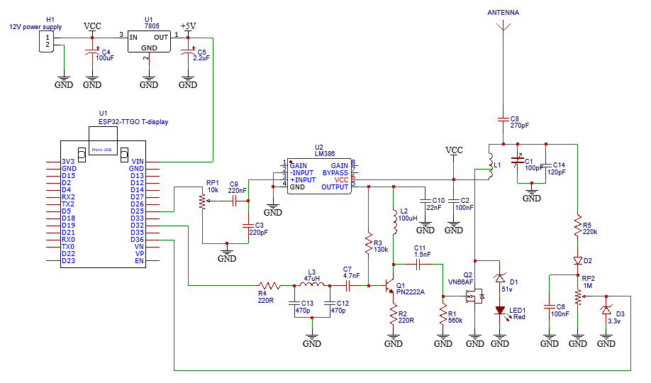
The diagram of the ESP32 with a C-class transmitterC12 + C13 + L3 is a low pass Butterworlf filter, the Q2 Base voltage is now the sinusoidal carrier signal.
R2 limits the Q2 gain, to lower distortion.
L2 is a tuned circuit with… the MOSFET input capacitor. VN66AF is about 50pF. VN66AF is hard to find now. It can be replaced by a pair of 2N7000 or BS170, in parallel connection. As these MOSFET, compared to a VN66AF, are half powerful and half input capacitor, it will be the same result replacing the VN66AF with 2 parallel connected 2N700 or BS170.
A IRF510 can also be used, however it has a 100pF input capacitor. So L2 may be adjusted to 47uH instead of 100uH. As it is a much more powerful MOSFET, may be the LM386 should be replace by a TDA2003 that allows a 18V power supply. I have not tested this configuration, as I do not own any IRF510 at the moment I write this paper.
L1 is coming from a ferrite frame tuning coil of an old radio. The small side is connected to power supply and the Drain, le large side to the antenna: this coil is like a step-up transformer. The voltage at the antenna can rise 200V!
This load is a tuned circuit. Depending of its quality factor, the Vds voltage can easily exceed the maximum MOSFET voltage, 60V, so a security must take place to limit the max Vds.D1 is a 51V Zener, I replace it with 2* 27V Zener wired in series. It limits the Vds under the 60V maximum permissible voltage for the MOSFET. When this security is active the LED1 is lighting.
As the antenna is seen as a capacitor, the C8 value must be respected. C1 is tuned to get the max voltage.
There is a way to have a look to the RF transmitted voltage level: R5 pickups the RF signal, D2 decodes it, D3 limits under the 3.3V allowed by the ESP32 inputs.
Vcc can be 9V, enough the transmitter broadcasts throughout the house. Total consumption is less than 400mA.
List of materials1. 1x ESP32 TTGO T-display or any ESP32 models with their own DAC
2. 1x 7805 5V voltage regulator for the ESP32 power supply
3. 1x LM386
4. 1x PN2222A or 2N2222A (the A is important for better performances)
5. 1x VN66AF or 2x in parallel wired 2N7000 or BS170
6. 1x 100uH coil,
7. 1x ferrite frame tuning coil of an old radio
8. 1x 100pF adjustable capacitor
9. Few resistors, capacitors, zeners….

Comments