

Hardware components | ||||||
 |
| × | 1 | |||
 |
| × | 1 | |||
 |
| × | 1 | |||
| × | 1 | ||||
 |
| × | 3 | |||
| × | 1 | ||||
| × | 1 | ||||
| × | 1 | ||||
| × | 1 | ||||
 |
| × | 1 | |||
| × | 1 | ||||
| × | 4 | ||||
 |
| × | 1 | |||
 |
| × | 1 | |||
Software apps and online services | ||||||
 |
| |||||
| ||||||
Hand tools and fabrication machines | ||||||
 |
| |||||
 |
| |||||
 |
| |||||
Have you ever wondered how those fancy robots that transport parts on assembly lines work? I saw such robots at Opel factory here in Poland, I asked a lot of questions and they explain to me how it works, I instantly understood that this is just a really advanced line follower. Instead of black tape there is magnetic strip and instead of light sensors there are magnetic sensors, there are also a lot of safety features and other smart things. But at this point I started thinking that maybe I can build my own smaller, cheaper, Arduino based and open source version of such a robot that will be able to smartly transport stuff around? Sounds like a big challenge, that’s what I like!
DesignFirst things first I designed it... on a paper! Yes on the paper with a pencil in my hand :) Why designing on a paper if you have awesome CAD software? There are a few advantages that I heard from other people and then confirmed them by myself. You are really free, there are no limitations on the paper, no distractions just blank space and a pencil that makes things really easy. It's also faster you don't have to worry about dimensions and the final shape if you don't like something that you drew you can just draw that again and when you see all of your drawings at once you can combine them together and come up with new ideas :) It was very easy to draw it on a paper to find an overall shape that I like and then jump to CAD to add some dimensions to my drawing. Really recommend this technique to everyone! Here are my drawings (those colourful lines on the right side is my brother's son creativity)
Of course, my drawings are not very good, and if you can draw you would make something better in 5 minutes but I used to be really bad at drawing and above example looks promising to me. Then I created a CAD design based on that drawing. I knew right from the beginning that some parts of this robot will be 3D-printed, but I didn't want to make it 100% 3D-printed and I wanted to experiment and try new things (as always). Finally, I decided to cut some parts on a laser cutter, but I don't have one and I never designed something for a laser cutting learned how to do that and ordered that online. As a material, I chose 4mm plywood (you can also use plexi or something similar). A front part of the robot is 3D-printed and hold all of the sensors, electronics and battery. Here are renders of my design which in my opinion look fantastic!
Next step was to order laser cutting of those wooden plates, I am from Poland so I found a Polish company that do that to save on shipping. If you want to find something around you just Google laser cutting and a name of your city you should easily find something around you. Remember to ask the company if they can adjust the offsets for those parts so that finger joints will fit perfectly (we have to do that because of a thing called kerf, you can read more about that here). Fortunately, I found a company that took care of that for me, thanks!
I was quite afraid because I have never designed for laser cutting and I have never used any laser cut parts before but it turned out beautifully :) DXF files for laser cutting can be found below in the attachment section.
To complete the chassis I had to print a front part on a 3D printer, that's the tool that I have so that wasn't a problem for me, if you don't have a 3D printer yet, consider buying one, they are quite cheap nowadays. You may be able to find one at school or library, or maybe one of your friends is 3D printing enthusiast. STL files can be found in the attachment section below. There are not any specific setting for 3D printing, I used 2 perimeters with 30% infill and 0.2mm layer height, you have to use support to print this part. It will take about 8 hours so be patient.
Once your print is finished you can clean it up and screw to the plywood parts but I decided to put some more work to it. Again that's something that I have never done before, I sanded down my print and paint it, sanded again and paint it then I used a car filler to make the surface perfect, then some more sanding and painting. It took a lot of time, but I also learned a lot, and just take a look at this shiny surface! It is perfect, you can't tell that it was 3D-printed at all! 2 days of painting and sanding, definitely worth it.
And here are laser cut parts and 3D-printed part prepared for assembling.
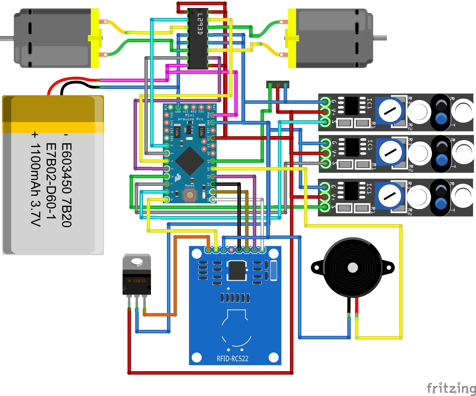
But this project is of course not just about the design. Everything is controlled by Arduino pro mini that is connected to the custom PCB that I designed in Fritzing (PCB layout and design files can be found in the attachments). To make it work on its own without human input there are also line sensors and RFID module to detect tags placed next to the line. H bridge that controls cheap and popular gear motors is L293D, small and easy to use. I also decided to add a buzzer to the circuit so that a robot can beep when certain RFID tag is detected. Everything is powered by 2 cell LiPo battery (7, 4V of nominal voltage). Because RFID module has to be powered with 3, 3V I had to add a voltage regulator on the PCB so that it supplies proper voltage to the module. There is also an ultrasonic sensor to detect obstacles, as they say, safety first! There was one problem, reading distance with HC-SR04 takes quite a lot of time in terms of microcontrollers so I designed another project (more info here) that makes it easy and fast to detect obstacles with this sensor. It is not necessary but definitely makes things a lot easier.
To build the PCB you need some tools and components (Arduino, L293D, some breakaway headers, battery connector, buzzer, 3, 3V voltage regulator). You can read more about how to make PCB at home and what kind of tools you need here
At the beginning, I wanted to mill my PCB on a CNC milling machine but I decided to use a method that I was familiar with called toner transfer. Above you can see toner transferred on to the copper board. Then I etched my PCB and clean the tonner. You also have to drill holes in it in order to put THC (Through Hole Components) inside.
Soldering was incredibly easy as for the DIY PCB, usually, it is much harder to solder because there is no solder mask* on it.
*Soldermask - is a thin lacquer-like layer of polymer that is usually applied to the copper traces of a printed circuit board (PCB) for protection against oxidation and to prevent solder bridges from forming between closely spaced solder pads. ~Wikipedia
There are 5 jumper wires on the bottom of the PCB (in Fritzing's PCB view those are labelled as blue cables), I really don't like using jumpers but with more complex circuits and single layer PCB, there is just no way to avoid them.
As I said to power this robot I will use 2 cell LiPo battery, you can use any other battery with similar voltage, you don't have to use specific capacity of the battery (the bigger the capacity the longer your robot will work on a single charge). I also soldered a socket to the PCB so that I can easily connect battery to it.
When everything is soldered it's time to test if it works by connecting a battery to it. Arduino LEDs should light up and there should be no smoke :)
If everything works fine we can do last soldering job with our PCB, we need to solder cables that we will later solder to the motors. It's better to make them a little bit longer than you need and cut later, you don't want them to be too short.
PCB is ready! If you have no experience with making a PCB, try to do one, it is not that hard. If you prefer to connect it with cables or a protoboard, feel free to do that but it may be hard to fit that into the front part of the robot. With PCB you can easily do that! We still need to connect all of the sensors to the PCB but firstly we will assemble the chassis and attach all of the sensors to it.
AssemblingFinger joints of laser cut parts fit perfect together but to make that really rigid and durable we have to use glue. That's a plywood so any wood glue will do the job. Make sure not to use too much glue and clean it in case of any leaks. It should dry for a few hours so we can take a break. Make sure that all of the parts are placed properly, there will be no way to change that once glue drys.
After a few hours, we can continue assembling our robot. It's time to attach the 3D-printed front part to the plywood. We wouldn't use glue for that, as they taught me during my CIT internship: using glue is unprofessional, forget about it (but I hope it's fine with wood). We will use screws, placed from the bottom of the robot, make sure that they are short (let's say 6mm long) so they wouldn't create any shorts on the circuits inside the 3D-printed part. The good thing about this way of attaching the front part to the plywood is that you can't see that from the top, you have to look under the robot, it makes it a lot better :) I recommend you to use washers to protect plywood from deformation.
That's how it should look so far, so clean and perfect!
Now we will mount motors and back wheel to the chassis. You will need some M3 screws for that. I also used some washers here to protect the plywood.
It's time to go back to the sensors, flip your robot grab some M3 screws and a screw driver.
Assembly done! Wasn't hard at all, pure pleasure. We can see the shape of the robot now with all of the sesnors and motors on it's place. We are really close to finish that but before final test we have to connect all of the sensors to the PCB.
ConnectionThis step can tak some time, it's not hard but really tricky to put all of the cables through tiny space of 3D-printed front part. I found that the best way is to connect cables to all of the sensors and modules, put them through holes in the front part and at then end connect to PCB.
I wanted to put all of the electronics for this project on the left side of the 3D-printed part, unfortunately, a battery turned out to be a little bit bigger than advertised and I had to put a battery on the left side and electronics on the right side. But that wasn't a big deal, everything fit perfectly into it.
Also remember to put in place ultrasonic sensor.
To easily turn the robot on and off I added a switch on the battery connector like so. There is also a hole in the back panel to put a switch inside it.
Before we will close back of the front part we have to upload code to the Arduino pro mini. We need to take out Arduino from the PCB and connect it to the computer with USB-UART converter. Code for Arduino can be found below. Everything about the code is explained in the comments and in the video. COde can be also found in the web editor
There is also a special program that I wrote in C# to generate tasks for this robot, it is called tasks planner (you can find.exe file below). It lets you easily generate tasks for the robot, copy them and paste to the Arduino IDE before uploading to the Arduino. To generate tasks for the robot you need to know id of RFID card, to obtain it you can build a simple circuit more info here.
Now we can close back of the front part with two flaps and screw them down. It may be tricky to fit all of the components inside, try to rearange them and put them in different possitions to close the flaps.
To screw that down you can use some short M3 screws and you don't need washers there. That's the last thing that we had to do. Our robot is finally ready for the final test! I spent so much time on building it, I am really happy that now I can see if it will work as I intended it to work :)
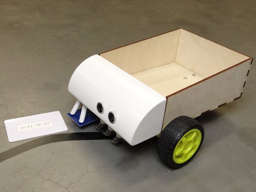
Here is how it looks like with all of the components on its place, electronics hidden in the front part and sensors mounted on the robot. The only down side is that battery charging may be difficult because you have to open a back flap to take it out. Simple solution for that would be to make a hole in the 3D part and stick out balancer cable of the battery through this hole.
I wasn't sure how to show you how this robot work or I should say how to do that right. The main purpose of this project is to build a cheap open-source robot that can smartly transport stuff around assembly lines and factories so I set up a simple assemble line and asked my dad and brother's son for help. Our goal was to put an item in the robot, grab it from the robot on a different station and put the one that already has a sticker on it and on the last station move one with a sticker to the warehouse. The simple task that imitates the assembly line and lets you easily test how it works.
I wanted to put black tape on the floor, but it wasn't reflective enaugh for my sensors so I used some cardboard. And we started testing, you can see that on the video (you can find it at the beginning of this project).
There was a lot of things that could go wrong in this project, but everything turned out perfectly. It works as I intended it to work, every step, the initial idea through the design and assembling went smoothly and incredibly good. When I said that there was a lot of things that could go wrong I really mean that. I have a lot of experience with 3D printing, programming and Arduino but that was the first time I drew my project on a paper which was great idea and I will do that more often for sure, I have never designed anything for laser cutting before, even though I have a certificate of a C# programmer I am not a master of it. And I managed to connect all of that together to create such a cool robot :) I hope you liked my project, if so don't forget to say few words about it in the comments, I am really curious what you think about it. If you have any questions, feel free to ask! Thanks for reading.
Happy making!


_t9PF3orMPd.png?auto=compress%2Cformat&w=40&h=40&fit=fillmax&bg=fff&dpr=2)


_3u05Tpwasz.png?auto=compress%2Cformat&w=40&h=40&fit=fillmax&bg=fff&dpr=2)

Comments