Saad Motahhir
Published © MIT

Arduino based MPPT Controller

Data’s Guide of “Development of a low-cost PV system using an improved INC algorithm and a PV panel Proteus model” research paper

AdvancedFull instructions provided48,230
Arduino based MPPT Controller

Things used in this project

Hardware components

Arduino UNO
Arduino UNO
×1
Electric Imp TDC-M20-36PV panel
×1
DC-DC Switching Boost, Inverting Regulator
×1
Resistor, 70 ohm
Resistor, 70 ohm
×1
Adafruit INA169 Analog DC Current Sensor
×1
Adafruit B25 0 to 25V Voltage Sensor Module
×1
Microchip TC4420 Driver
×1

Software apps and online services
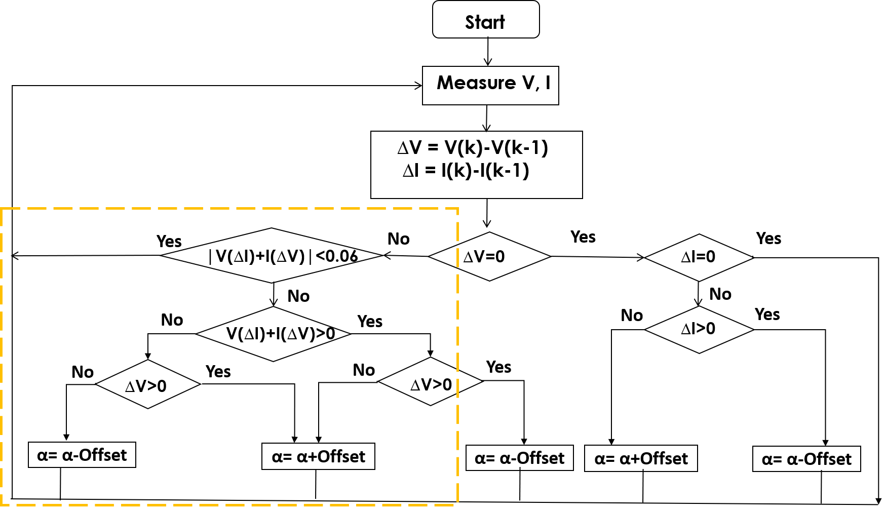
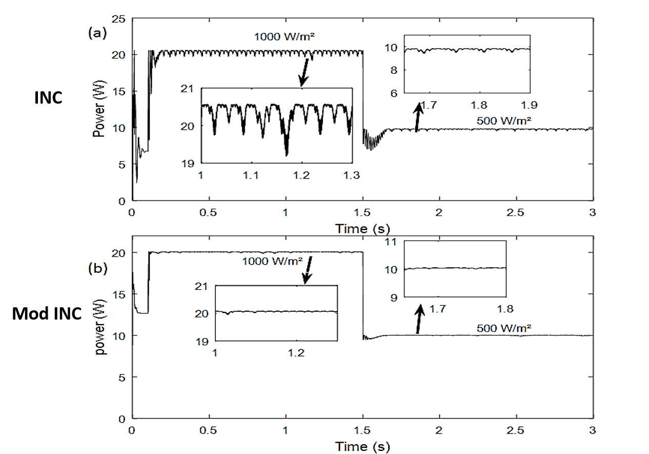
Arduino IDE
Arduino IDE
Proteus 8.6

Story

Read more

Schematics

MPPT-in-Proteus

Download data from gethub

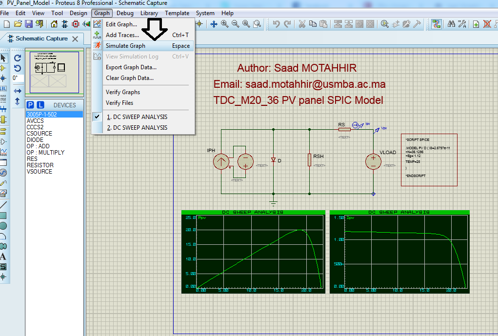
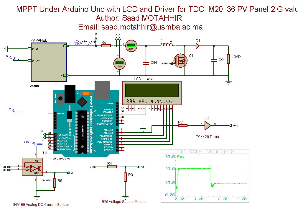
Proteus PV panel model simulation

• Please, open \Proteus\Proteus_PV_Panel_Model.
• Please, go to graph menu and click on simulate graph as follows:

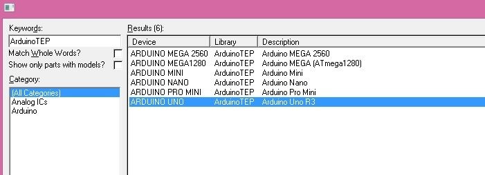
Add Arduino into Proteus:

• Unzip Arduino Library for Proteus.rar file, you will find two files in it.
• These two files are named as ArduinoTEP.LIB and ArduinoTEP.IDX.
• Copy these two files and place them in the libraries folder of your Proteus software.
• Now, restart your Proteus software and in components section search for ArduinoTEP as shown in below figure:

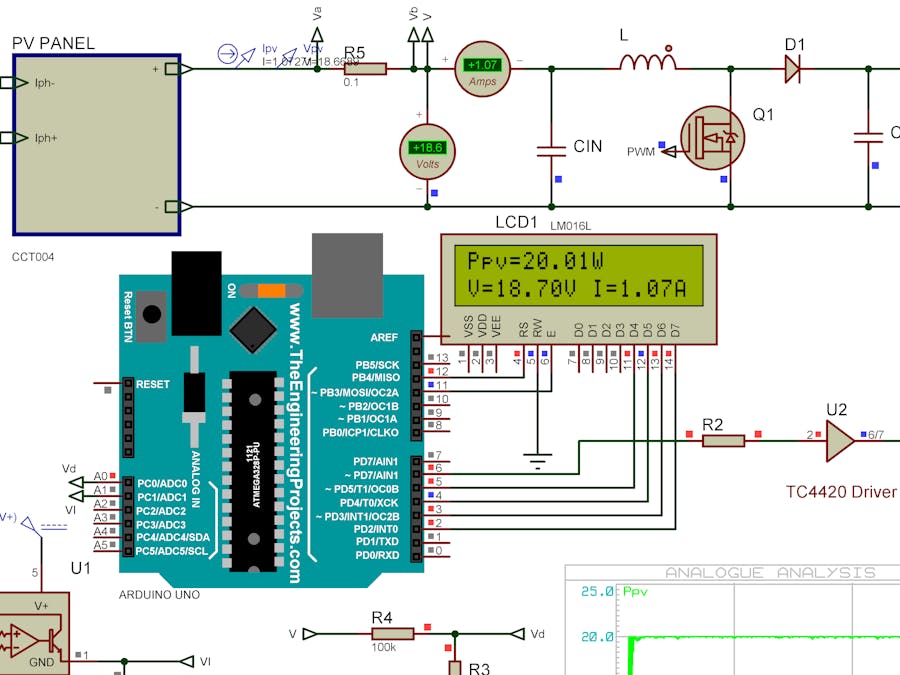
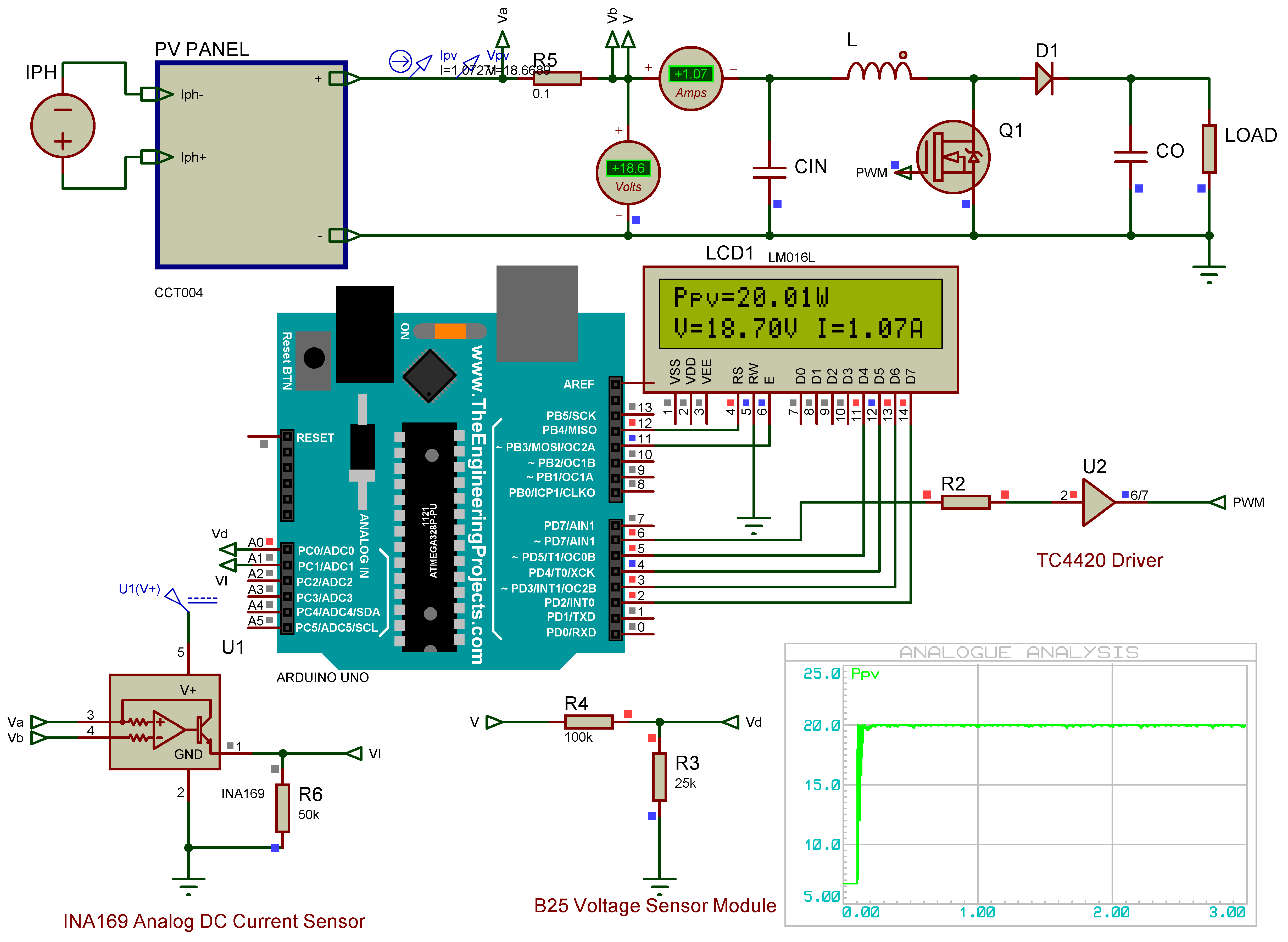
Simulate the MPPT controller in Proteus under stable irradiance

• Please, open Proteus\Proteus_MPPT_stable irradiance
• Load the .hex file in the Arduino Uno.
• Click on play to simulate the PV system or go to graph menu and click on simulate graph to generate Ppv(t) curve.

Simulate the MPPT controller in Proteus under variable irradiance

• Please, open Proteus\Proteus_MPPT_Irradiance Variation
• Load the .hex file in the Arduino Uno.
• Click on play to simulate the PV system or go to graph menu and click on simulate graph to generate Ppv(t) curve.

Costless and effective Embedded system based control for PV system

As shown in the incremntal conductance (INC) structure (figure below), it contains several division computations which require a stronger microcontroller including large memory, high clock frequency, and floating-point computation, and this reduces the opportunity to use a low-cost development board as Arduino UNO which is based on ATMEGA328P because it does not contain a hardware divider, but it provides a one-chip 2 cycle multiplier as shown in the figure below (datasheet of ATMEGA328P). Therefore, to design a costless and effective MPPT embedded software, a modified INC algorithm is presented through the elimination of all division computations occurring in the conventional NC method. As a result, the complication of the algorithm operation can be reduced and consequently, minimize the real-time processing with faster response. This, makes the utilization of low-cost microcontrollers possible.

The experimental setup of the PV system using Arduino

Conventional Incremental conductance algorithm

Modified Incremental conductance algorithm

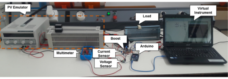
Experimental results

Figure below (a) and (b) presents the experimental results of both methods under fast varying of insolation (from 1000 W/m2 to 500 W/m2). A zoom in the results is made. As shown in (a), the conventional method generates more oscillations around the peak of power compared to the modified method as presented in (b). On the other hand, the modified method presents a faster tracking speed with response time equals to 0.1 s which is very lower than the response time obtained by the conventional method (0.36 s).

Code

PandO_Code.ino

C/C++
Below the code of perturb and observe algorithm, to compile it, please go to "Sketch" menu and click on "Export compiled Binary". Then the ".hex" will be generated in the Sketch Folder.
/*****************************************************************************
         Copyright  Motahhir  All Rights Reserved
*****************************************************************************/

/*****************************************************************************
   Header Files included
 *****************************************************************************/

/******************************************************************************
   PROJECT :  MPPT (P&O) implementation
   Function : P&O Arduino Code
 ******************************************************************************
 *                                                                            *
    Written by  :  Saad Motahhir                       Date : 09/10/2016
 *                                                                            *
    Email : saad.motahhir@usmba.ac.ma
 ******************************************************************************
   MODIFICATION LOG:
 ******************************************************************************
   Modified by :                                           Date :
   Comments :
 ******************************************************************************/
#include <LiquidCrystal.h>
LiquidCrystal lcd(12, 11, 5, 4, 3, 2);

float sensorValue1 = 0;
float sensorValue2 = 0;
float voltageValue = 0;
float currentValue = 0;
float Power_now = 0, Power_anc = 0, voltage_anc = 0;
float delta = 3;
float pwm = 128;
void setup()
{
  pinMode(6, OUTPUT);
  lcd.begin(16, 2);
}

void loop()
{
  sensorValue1 = analogRead(A0);
  sensorValue2 = analogRead(A1);
  voltageValue = (sensorValue1 * 5.0 / 1023.0) * 5;
  currentValue = (sensorValue2 * 5.0 / 1023.0);
  lcd.setCursor(0, 0);
  Power_now = voltageValue * currentValue;

  lcd.print("Ppv=");
  lcd.print(Power_now);
  lcd.print("W");
  lcd.print(pwm);
  lcd.setCursor(0, 1);
  lcd.print("V=");
  lcd.print(voltageValue);
  lcd.print("V I=");
  lcd.print(currentValue);
  lcd.print("A");


  if (Power_now > Power_anc)
  { if (voltageValue > voltage_anc)
      pwm = pwm - delta;
    else
      pwm = pwm + delta;
  }
  else
  {
    if (voltageValue > voltage_anc)
      pwm = pwm + delta;
    else
      pwm = pwm - delta;
  }
  Power_anc = Power_now;
  voltage_anc = voltageValue;
  if (pwm < 20)
    pwm = 20;
  if (pwm > 150)
    pwm = 150;

  analogWrite(6, pwm);
}

INC_Code.ino

C/C++
Below the code of incremental conductance algorithm, to compile it, please go to "Sketch" menu and click on "Export compiled Binary". Then the ".hex" will be generated in the Sketch Folder.
/*****************************************************************************
         Copyright  Motahhir  All Rights Reserved
*****************************************************************************/

/*****************************************************************************
   Header Files included
 *****************************************************************************/

/******************************************************************************
   PROJECT :  MPPT (INC) implementation
   Function : INC Arduino Code
 ******************************************************************************
 *                                                                            *
    Written by  :  Saad Motahhir                       Date : 09/10/2016
 *                                                                            *
    Email : saad.motahhir@usmba.ac.ma
 ******************************************************************************
   MODIFICATION LOG:
 ******************************************************************************
   Modified by :                                           Date :
   Comments :
 ******************************************************************************/
#include <LiquidCrystal.h>
 LiquidCrystal lcd(12, 11, 5, 4, 3, 2);

float sensorValue1 = 0;
float sensorValue2 = 0;
float voltageValue = 0;
float currentValue = 0;
float Power_now = 0, Power_anc=0, Current_anc =0,Voltage_anc=0, deltaI=0, deltaV=0 ; 
float delta = 1.4;                 
float pwm = 128;                        
void setup() 
{
  pinMode(6, OUTPUT);
  lcd.begin(16, 2);
}

void loop() 
{
  sensorValue1 = analogRead(A0);
  sensorValue2 = analogRead(A1);
  voltageValue= (sensorValue1 * 5.0 /1023.0) *5;
  currentValue= (sensorValue2 * 5.0 /1023.0);
  lcd.setCursor(0, 0);
  Power_now = voltageValue * currentValue;
  
  lcd.print("Ppv=");
  lcd.print(Power_now);
  lcd.print("W");  
  lcd.setCursor(0, 1);
  lcd.print("V=");
  lcd.print(voltageValue);
  lcd.print("V I=");
  lcd.print(currentValue);
  lcd.print("A");
  deltaI= currentValue-Current_anc;
  deltaV= voltageValue-Voltage_anc;
 if(deltaV==0)
  { if(deltaI==0)
     {// nothing to do
     }
   else 
    { if(deltaI>0)
       pwm=pwm-delta;
     else
       pwm=pwm+delta;
    }
  }
 else
  { if((voltageValue*deltaI)+(currentValue*deltaV)==0)
     {// nothing to do
     }
  
    else
     { if((deltaI/deltaV)+(currentValue/voltageValue)>0)
        
         pwm=pwm-delta;  
    
      else
        pwm=pwm+delta;
     
     }
  }
      
Voltage_anc= voltageValue;
Current_anc= currentValue;
Power_anc=Power_now;
if(pwm > 240)
   pwm=240;
if (pwm < 15)
   pwm=15;
 analogWrite(6, pwm);
}

Credits

Saad Motahhir

Saad Motahhir

2 projects • 48 followers

Comments