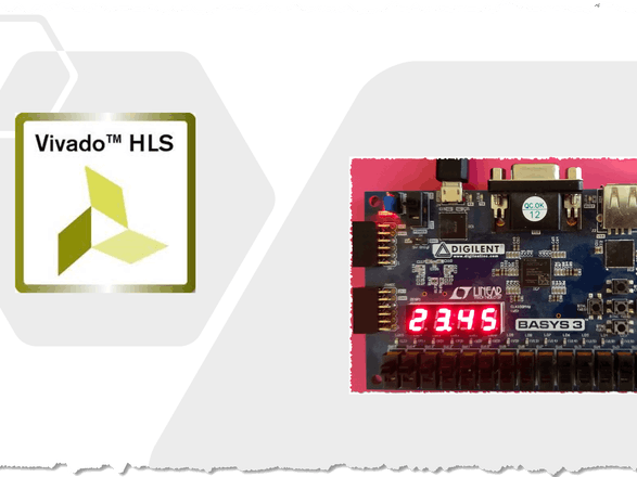
Abstract: In this small project I am going to display a floating-point number on 4-digit seven-segments using HLS. If you are interested in designing with HLS, please refer to here or here.
Driving a 7-segment display consisting of several segments is one of the traditional projects in learning any hardware or software language targeting hardware design and control.
Here, I am going to show a floating-point number on a 4-segment display using Vivado-HLS. Although writing the 7-segment driver in HDLs is not complicated, describing this driver in HLS is instructive. Also, you can compare that with the equivalent HDL code and find out how it is easy to use HLS to implement a wide range of digital circuits.
During this implementation, I am going to explain two main concepts in describing a sequential circuit in HLS. These two concepts are delay and execution order. Whereas I utilise a pipelined loop to implement a timing delay in HLS, I propose using a state machine to impose a specific execution order in HLS.
Let’s have a look at the 7-segment structure on the Digilent Basys-3 board. This board contains a four-digit common anode 7-segment display, as shown in the following figure.
Two groups of lines control these segments. The first group send a code pattern to the segments which are shared among all of them. The second group determine which segment is enabled, which should show the code available on the data lines. The following figure shows the configuration of these lined for the Basys3 board.
To display four digits on the segments simultaneously, we should multiplex the data lines among them using the control lines to enable one segment at the time. The following timing diagram shows this mechanism.
To perform this time-multiplexing mechanism, we need a function implementing a timing delay to provide the refresh period. The following code can do this task.
bool delay(int n) {
#pragma HLS INLINE off
  static bool dummy = 0;
  for ( int i = 0; i < n; i++) {
    for ( int j = 0; j < n; j++) {
#pragma HLS pipeline
      dummy = !dummy;
    }
  }
  return dummy;
}
The parameter n (which is the function argument) can be used to change the timing delay. The following figure shows the Vivado-HLS synthesis report after synthesising this code when n = 500. As can be seen, the initiation interval (II) is one. Also, the function latency is (n^2+2) clock cycles which are 250002 in this case. If n = 100Mhz then the delay of the function is about 2.5ms.
Now we need a function to implement the time multiplexing; for this purpose, we can use a state machine with four states as follows:
void display_driver(
  ap_uint<4> a, ap_uint<4> b, ap_uint<4> c, ap_uint<4> d,
  ap_uint<8> &segment_data,
  ap_uint<4> &segment_enable,
  bool       reset)
{
  static ap_uint<2> state = 0;
  while(reset == 0) {
    switch (state) {
    case 0:
      segment_data   = svn_sg_code[a];
      segment_enable = 0b0111;
      state = 1;
      delay(500);
      break;
    case 1:
      segment_data   = svn_sg_code[b] & 0b01111111;
      segment_enable = 0b1011;
      state = 2;
      delay(500);
      break;
    case 2:
      segment_data   = svn_sg_code[c];
      segment_enable = 0b1101;
      state = 3;
      delay(500);
      break;
    case 3:
      segment_data   = svn_sg_code[d];
      segment_enable = 0b1110;
      state = 0;
      delay(500);
      break;
    }
  }
}
Finally, a top-function should embrace all the tasks. The following top-function displays a floating-point number which is 23.45 on the 7-segments.
void  display_float(
  ap_uint<8> &segment_data,
  ap_uint<4> &segment_enable,
  bool        reset) {
#pragma HLS INTERFACE ap_none port=segment_data
#pragma HLS INTERFACE ap_ctrl_none port=return
#pragma HLS INTERFACE ap_none port=segment_enable
#pragma HLS INTERFACE ap_none port=reset

  float a = 23.45;
  unsigned int a_int = a;

  float b = a - a_int;
  unsigned int a_int0 = a_int%10;
  a_int = a_int /10;

  unsigned int a_int1 = a_int%10;
  unsigned int b_int0 = b*10;

  b = b*10 - b_int0;
  unsigned int b_int1 = b*10;

  display_driver(a_int1, a_int0, b_int0, b_int1, segment_data,
  segment_enable, reset);
}
After using the Vivado toolset for logic synthesis, we can program the board and check the result.


Comments