

ATTENTION USE A GOOD QUALITY 12 V POWER SUPPLY. Otherwise max31865 will not work properly.
A popular way to produce hot water is “the sun”. In winter (lets say November through March), hot water is produced by the burning of diesel. The burner stops at 60 degrees. (After three starts the burner stops at 60 degrees but the temperature will reach about 70 degrees.) The hot water pump starts at 40 degrees. The maximum temperature in the hot water tank is set to 60 degrees. (1500 litres of hot water is enough for 6 apartments). The pump starts to circulate the water between the burner and the hot water tank by bringing the hot water temperature from ambient temperature to 50. After reaching the desired temperature in the hot water tank, the pump continues to run. There is a difference of about 10 degrees that burner’s boiler temperature must drop down to start the burner again.
Once the burner is switched off and starts to cool down amounts of heat is transferred from the hot water tank to the burner’s boiler. The pump, if the temperature is greater than 40 degrees, continues to run. Here the digital thermostat stops the pump to run when it detects that the temperature of the hot water tank is higher than the burner temperature If users use hot water and temperatures in burner resist, the digital thermostat allows the pump to operate again.
Burner’s pump must be stopped when the temperature in the boiler is greater than the burner's. The main controller uses two PT1000 interfaced with max31865 interface to a dspic30F4013. A Nokia 5110 like small screen reports the actual temperature values and the state of the controller and the pump. A relay acts as a switch for the pump or the magnetic valve. Usually, this device is installed in the basement near the burner -boiler but you can install it over a 100 meters.
The controller senses the temperatures of the boiler and the hot water tank through PT1000 sensors. These sensors are droved with max31865 chip. A chip from “Maxim Integrated” a RTD-to-Digital Converter. These chips use the SPI Interface to communicate with the dspic. The max31865 uses a CS pin to be enabled. The schematic for the max31865 is typical and described in the datasheet of the Max31865.
One sensor is stacked onto the output pipe of the boiler and one is stacked on the hot water tank (usually hot water tanks has multiply inlets for thermometers – one will be occupied by the PT1000).
Table 1. controller sate and explanation1 H.W.T AtMax Hot water tank have reach the max programmed temperature. Hot water pump is off
2 Pump tmp low The burner-boiler temperature is lower then the programmed temperature to start the hot water pump. Hot water pump is off
3 reserved
4 H.W.T high The temperature of the H.W.T is higher then burner boiler. Hot water pump is off
5 Burner high The burner-boiler temperature is higher than the temperature of the programmed pump start temperature and the H.W.T temperature. The hot water pump is on.
-----------------------------------------------------------------------
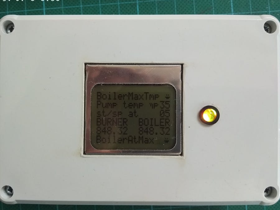
The screen of the controller is a graphic LCD 84x48 (Nokia 5110 compatible screen) With 8x5 pixel characters in 84x48 pixel matrix there are 6 lines with 15 characters width for custom messages.
At screen line 1 H.W.T Temp shows the max programmed temperature of Hot water tank eg. 52 when HWT[4] reaches this value the controller shut off the hot water pump. The temperature in the tank must drop by 2OC to start the pump again. (The value of2OC is from experience and in this firmware is embedded) During this time the value of the maximum temperature is alternately displayed with a special character, indicating this state. (Static const byte glyph[] are declared in “ void InitLCD() “ function that initialize the LCD module.
Line 2 on the screen shows the temperature of the burner-boiler above it will start the hot water pump.This value can be changed through the embedded web page.
Line3 on the screen show “st/sp” the time interval to start or stop the pump to avoid the pump’s stress from immediate start/stops
Line 4 on screen show“BURNER H.W.T.” These are the labels for values in line 5
Line 5 on the screen show the actual values of temperatures of burner-boiler and H.W.T. A value of 848 means that no sensor is connected and a value of -231 means that the sensor is short circuit.
Line 6 on the screen shows a string indicating the state of the controller (see table 1) the last character in line 6 is a glyph flashing once a second indicating the controller is running properly.
The hardware Timer1initialized for 1 sec tick. Library for RTD initializes the max31865 chips using a 2 wire sensors.
If you like a thermostat with remote monitor the see my other projects


Comments