


Hardware components | ||||||
 |
| × | 1 | |||
 |
| × | 1 | |||
 |
| × | 1 | |||
 |
| × | 1 | |||
 |
| × | 1 | |||
 |
| × | 1 | |||
 |
| × | 1 | |||
 |
| × | 1 | |||
#quickstart #complete #template #translate #interface #normalize
This quickstart project provides a complete template to get the LittleBits Arduino working in seconds, which is great for people familiar with LittleBits, but unfamiliar with Arduino. The code configures all of the input and output pins so that they work seamlessly with LittleBits. Special bonuses:
- Video explanation: https://www.youtube.com/watch?v=GbOGz2W2jBE - The code fixes the "4x problem" where analog outputs values are 4x input values
- The code sends input and output values to the Serial Monitor for easy debugging
- You can use the Arduino to build any digital logic you like using AND, OR, NOT, etc.
- You can modify this code to create any project you like
Duration: 10 minutes
STEP 1 : Check out the video explanation
1 Watch this brief video that explains how this quickstart project works. Watching it now should save you time later.
STEP 2 : Set up the software
2.1 Download and install the Arduino IDE (the computer program to communicate with Arduino) from https://www.arduino.cc/en/Main/Software
2.2 After you open the program, delete the blank code and copy & paste the quickstart code, available above and on GitHub:
https://github.com/mikimer/LittleBits_projects/blob/master/quickstart.ino
STEP 3 : Set up the hardware
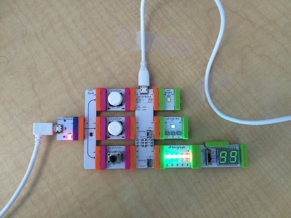
3 Create the LittleBits circuit from the photo above.
A few notes:
- Feel free to use as few or as many inputs and outputs as you like -- you don't need to use all 3 inputs and all 3 outputs.
- Feel free to use different types of inputs and outputs; however, note that the Top and Middle inputs are configured to be digital whereas the Bottom input is configured to be analog.
STEP 4 : Get the Arduino code working
Picture 3
Picture 2
4.1 Plug the USB cable into your computer and the LittleBits Arduino
4.2 Select the board as "Arduino Leonardo" and the port as "usbmodem". If you don't see usbmodem as a port option, try plugging into a different USB port.
4.3 Click the upload button.
4.4 Enjoy! You can now manipulate logic and send & receive signals with your LittleBits Arduino!


Comments