// -----------------------------------------------------------------
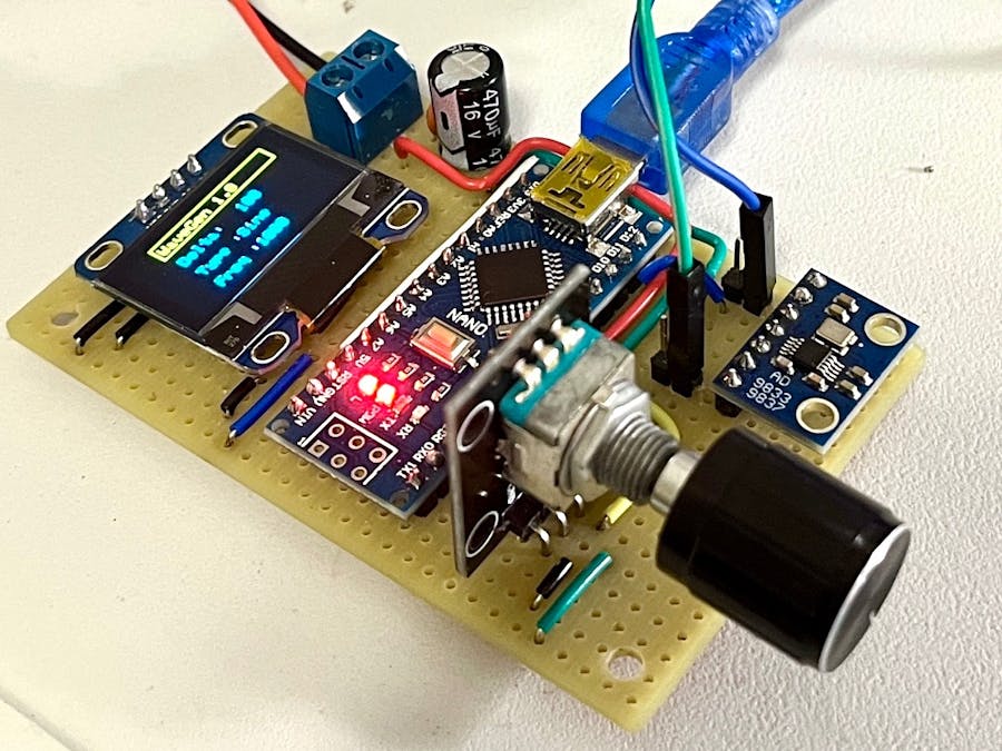
// A simple sine-square-triangle signal generator
// Using GY-9833 frequency generator board, with OLED display.
//
// Pushbutton sets waveform; rotary encoder sets frequency
// Range 10 Hz - 1 MHz
// Michael Willems
// Contact: michael@willems.ca
// Date: 16/12/2022
// -----------------------------------------------------------------
// -----------------------------------------------------------------------------------------
// DECLARATIONS:
// -----------------------------------------------------------------------------------------
// Include the required Arduino libraries:
#include <Wire.h> //for I2C
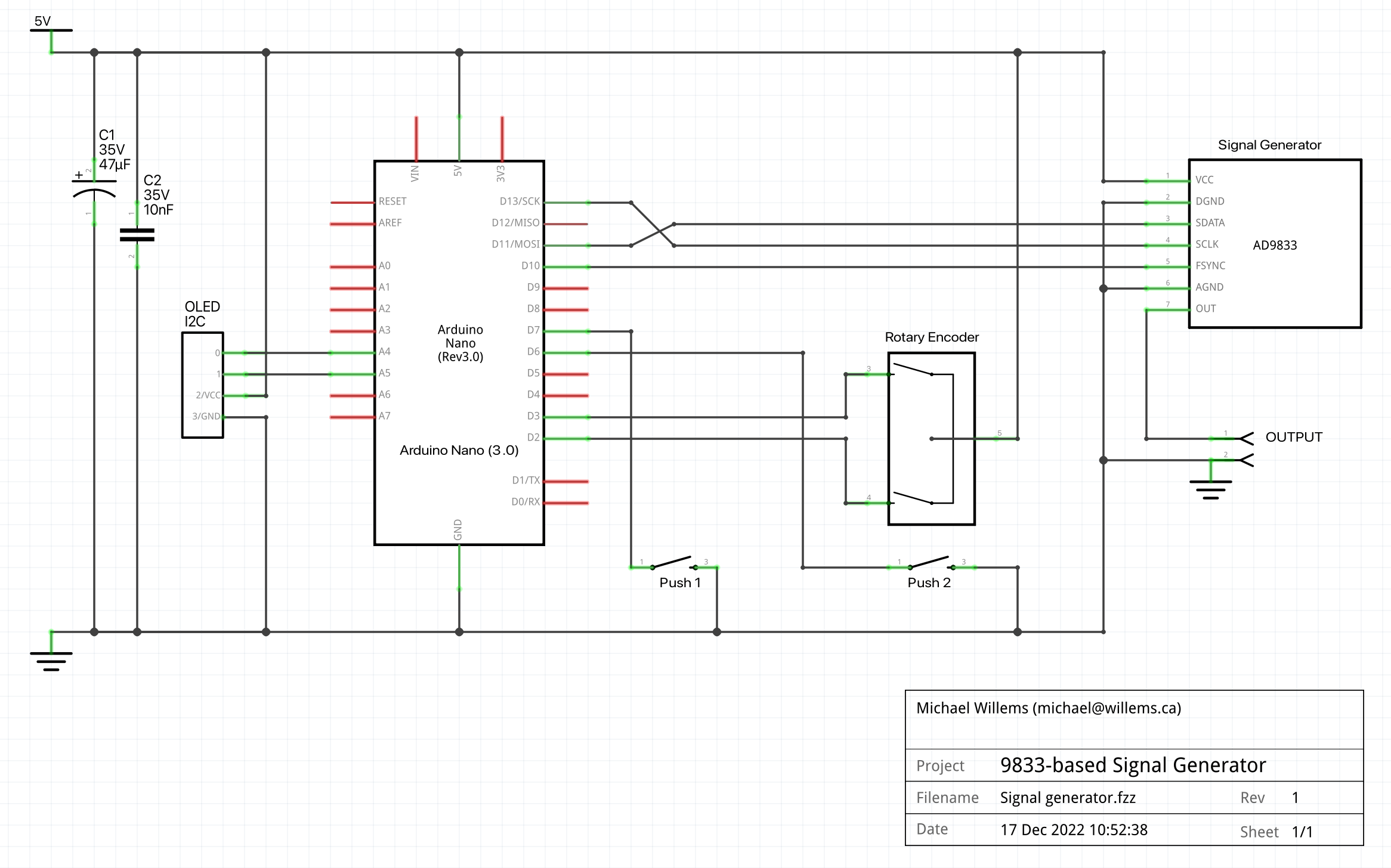
#include <MD_AD9833.h> //for Frequency Generator
#include <Encoder.h> //for Rotary Encoder
// Pins for SPI comm with the AD9833 IC
#define DATA 11 ///< SPI Data pin number
#define CLK 13 ///< SPI Clock pin number
#define FSYNC 10 ///< SPI Load pin number (FSYNC in AD9833 usage)
MD_AD9833 AD(FSYNC); // Hardware SPI
// Include the OLED stuff:
#include <Adafruit_GFX.h>
#include <Adafruit_SSD1306.h>
#define SCREEN_WIDTH 128 // OLED display width, in pixels
#define SCREEN_HEIGHT 64 // OLED display height, in pixels
#define OLED_RESET -1 // Reset pin # (or -1 if sharing Arduino reset pin)
//#define SCREEN_ADDRESS 0x3C //< See datasheet for Address; 0x3D for 128x64, 0x3C for 128x32
#define SCREEN_ADDRESS 0x3C //< See datasheet for Address; 0x3D for 128x64, 0x3C for 128x32
Adafruit_SSD1306 display(SCREEN_WIDTH, SCREEN_HEIGHT, &Wire, OLED_RESET);
//the rotary encoder:
Encoder Knob(2,3); // The (interruptable) pins for "clock and data"
long KnobPosition = 0;
long newKnobPosition;
//the rotator knob pushbutton:
int button2 = 6;
long buttonTimer2 = 0;
long buttonActive2 = false;
long longPressTime2 = 100;
long longPressActive2 = false;
// the regular (waveform select) button:
int button=7; // for selecting waveform
long buttonTimer = 0; // to see how long the button has been pressed
boolean buttonActive = false; // to set if the button is currently pressed
long longPressTime = 100; // How long to push button before we activate button mode?
boolean longPressActive = false;
// Other declarations:
unsigned long counter; // for flashing on-board LED with 1s frequency
int activeled = 12 ; // for heartbeat LED, if we bother to hook it up
byte wavetype = 1;
long Freq = 1000; // starting frequency
byte oldWavetype = 0;
long oldFreq = 0;
char wavemode = 1;
byte changepower = 0;
long delta = 1;
// -----------------------------------------------------------------------------------------
// THE SETUP (RUNS ONCE):
// -----------------------------------------------------------------------------------------
//
void setup() {
pinMode(activeled, OUTPUT);
pinMode(button,INPUT_PULLUP); //so making it negative activates the button
pinMode(button2,INPUT_PULLUP); //so making it negative activates the button
counter = millis();
Serial.begin(9600);
if(!display.begin(SSD1306_SWITCHCAPVCC, 0x3C)) { //if display fails, stop
Serial.println("No display found");
for(;;);
}
Serial.println("Display found OK");
AD.begin(); // start the generator board
display.display(); // show OLED logo
delay(1000);
display.clearDisplay();
display.display();
display.setTextSize(2); // Draw 2X-scale text
display.setTextColor(SSD1306_WHITE);
display.setCursor(0,0);
display.println(F("SYSTEM"));
display.setCursor(0,20);
display.println(F("INITIATED"));
display.setCursor(0,40);
display.println(F("& READY"));
display.println();
display.display();
delay(1000);
display.clearDisplay();
displaythelabels();
AD.setMode(MD_AD9833::MODE_SINE);
AD.setFrequency(MD_AD9833::CHAN_0, Freq);
}
// -----------------------------------------------------------------------------------------
// THE LOOP:
// -----------------------------------------------------------------------------------------
//
void loop() {
// First, the "every half second" stuff:
if ((millis() - counter) > 500) { //was 500
digitalWrite (activeled,!(digitalRead(activeled))); //the heartbeat LED
displayvalues(wavetype, Freq, oldWavetype, oldFreq); //display if changes have occurred
counter = millis();
}
// Now the "always" part of the loop:
// Now check the WAVETYPE button: is it pressed? If so, then change wavetype
if (digitalRead(button) == LOW) {
if (buttonActive == false) {
buttonActive = true;
buttonTimer = millis(); // i.e. start the timer
}
if ((millis() - buttonTimer > longPressTime) && (longPressActive == false)) {
longPressActive = true;
//Now change the wavetype (1-2-3-4 is sine, triangle, square, off)
wavetype = wavetype+1;
if (wavetype>4){
wavetype=1;
}
}
} else {
if (buttonActive == true) {
if (longPressActive == true) {
longPressActive = false;
}
}
buttonActive = false;
}
// Now check the CONTROLLER button: is it pressed? If so, change delta effected by turning rotator knob.
if (digitalRead(button2) == LOW) {
if (buttonActive2 == false) {
buttonActive2 = true;
buttonTimer2 = millis(); // i.e. start the timer
}
if ((millis() - buttonTimer2 > longPressTime2) && (longPressActive2 == false)) {
longPressActive2 = true;
//Here, do the things you need to do to set the delta:
changepower = changepower + 1; // meaning delta is 10^changepower
if (changepower>5){
changepower=0;
}
switch (changepower) {
case 0: delta = 1; break;
case 1: delta = 10; break;
case 2: delta = 100; break;
case 3: delta = 1000; break;
case 4: delta = 10000; break;
case 5: delta = 100000; break;
}
// now display the new delta (change amount per click):
display.fillRect(65, 20, 35, 15, 0);
display.setTextSize(1);
display.setCursor(65,20);
display.println(delta);
display.display();
}
} else {
if (buttonActive2 == true) {
if (longPressActive2 == true) {
longPressActive2 = false;
}
}
buttonActive2 = false;
}
// read the knob position. Has it changed? Then change frequency
// by the delta amount set by the controller pushbutton (1 Hz, 10 Hz, 100 Hz, etc)
newKnobPosition = Knob.read()/4;
if (newKnobPosition != KnobPosition) {
Freq = Freq + (newKnobPosition * delta) - (KnobPosition * delta);
if (Freq<10) {
Freq=10;
}
KnobPosition = newKnobPosition;
}
} // end of loop
// -----------------------------------------------------------------------------------------
// THE FUNCTIONS:
// -----------------------------------------------------------------------------------------
void displaythelabels() {
display.clearDisplay();
display.display();
display.setTextSize(1);
display.display();
// the display values stuff:
display.drawRect(21, 1, 100, 14, 1);
display.setTextColor(SSD1306_WHITE);
display.setCursor(24,5);
display.println(F("MVW SigGen 1.0"));
display.setTextColor(SSD1306_WHITE);
// now delta and type and frequency labels:
display.setCursor(24,20);
display.println(F("Delta: 1"));
display.setCursor(24,35);
display.println(F("Type : "));
display.setCursor(24,50);
display.println(F("Freq : "));
//and now activate it all!
display.display();
}
void displayvalues(byte W, long F, byte OW, long OF){
String wavestring;
//show only changed type/freq:
if ((F != OF) || (W != OW)) {
display.setTextSize(1);
display.fillRect(65, 35, 50, 25, 0);
display.setCursor(65,35);
switch (W) {
case 1: wavestring = "Sine"; break;
case 2: wavestring = "Triangle"; break;
case 3: wavestring = "Square"; break;
case 4: wavestring = "Off"; break;
}
display.println(wavestring);
display.setCursor(65,50);
display.println(Freq);
display.display();
//Now change the chip output waveform:
switch (W) {
case 1: wavemode = MD_AD9833::MODE_SINE; break;
case 2: wavemode = MD_AD9833::MODE_TRIANGLE; break;
case 3: wavemode = MD_AD9833::MODE_SQUARE1; break;
case 4: wavemode = MD_AD9833::MODE_OFF; break;
}
AD.setMode(wavemode);
AD.setFrequency(MD_AD9833::CHAN_0, Freq);
oldWavetype = wavetype;
oldFreq = Freq;
delay(50);
}
}


Comments