


Hardware components | ||||||
 |
| × | 1 | |||
 |
| × | 1 | |||
Software apps and online services | ||||||
 |
| |||||
Moving beyond single bus 255 device limits can be overcome using several techniques. One common approach is to group devices on separate control buses and re-amalgamate io from each bus into a central control process. This method works well with circuit board level systems and network meshed microcontrollers but unfeasible when using power line and wireless control protocols in close proximity.
Ring Counter
A rather simple but reliable approach is to use ring counters. In this design data is cascaded from one f/f to the next at incoming clock speed. The maximum number of output pins (control points) depends on number of flip flops and fan-out capabilities of gate/buffer chips. Most 74LS series gates have a fanout of 10. Using these in conjunction with high density FPGA's such as the Xilinx Spartan can reliably drive approx 2,000 GPIO io pins on one bus. The ring counter can be controlled and read by microcontroller GPIO io pins such as the GPIO on a Raspberry Pi.
Flip Flops in Ring Counter Configuration
Data Table
Automation Controllers
For practical applications ring counters can be used for automation and control systems such as the DIO120 human/computer interface controller. Massive io capability of this framework provides hundreds and thousands of control points needed for full house, business and or multi dwelling automation systems.
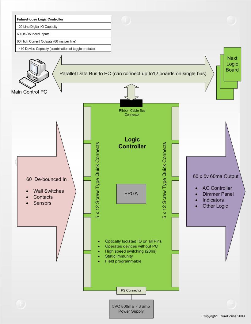
Logic Process Diagram for DIO120 Controller Board
GPIO pins from master controller are used to control Clear, Clock and Enable lines required to run ring counter.
Individual output states (control points) can be toggled by sending appropriate number of pulses on clock line until desired bit is reached. Data (word size based on size and number of gates) is then strobed via tri-state buffers to output state memory F/F's or other registers.
Example output control sequence:
Sub ToggleDev(BitNumber)
  Out(GPIO_CLEAR_0)
    For i = 0 to BitNumber
        Out(GPIO_CLOCK_0)
   Next
Out(GPIO_ENABLE_0)
Out(GPIO_CLEAR_0)
Reading Input Data
Similarly, ring counters can be used to read data residing on output state registers by sequentially enabling tri-state buffers and reading corresponding data back to the control system.
Example read input control sequence:
Function ReadData(BusData)
  Out(GPIO_CLEAR_1)
    For i = 0 to NumberOfRegisters
        Out(GPIO_CLOCK_1)
       busWord = busWord +  In(GPIO_BYTE)
   Next
  Out(GPIO_CLEAR_1)
Return busWord
Software Libraries
Use FAC DeviceSphere meshing libraries or develop your own simple input/output commands based on examples provided here.
Circuit Design
Circuit can be designed using individual components for flip flips and gates. Or in the case of massive IO, incorporation of FPGA'a is more feasible.
Early prototype of massive io interface using 74 series TTL chips. (128 control points per board. Max 8 boards)
DIO120 production FPGA human/computer interface board (120 control points per board. Max 10 boards). Shown here with Spartan 3 FPGA, 60 optically isolated darlington pair 80ma outputs and 60 optically isolated one shot switch debouncing inputs.
FPGA circuit design
FPGA's (Field Programmable Logic Array) provide millions of programmable gates required for hi density io (massive io). As seen in previous picture of early prototype. Four boards of this size are incorporated into one DIO120 FPGA board. In comparison, the wire wrap build took six months as opposed to 3 weeks using FPGA design technology.
DIO120 Platform
DIO120 is a platform that provides expanded industrial io connectivity and signal conditioning. 11 GPIO pins from a microcontroller can control up 120 GPIO pins per board. Up to 8 boards can be daisy chained on a single bus. Resulting in only 11 microcontroller pins required to control 1200 devices (channels).
The DIO120 comes preconfigured in ring counter mode and is ready to support human/computer interface mode. With this mode, humans can operate outputs via momentary contact switches/buttons without depending on a microcontroller or software. At the same time, master controller and core logic participate in control and monitoring of all outputs.
If you have your own FPGA or other means of addressing external io of the board. 8 x 24 pin headers can be used to connect your own control circuitry. In doing this you can take advantage of the robust connectivity and signal condition provided by the base board.
DIO120 Automation Install4 controllers makeup digital portion of structured whole house automation system.
- 200 x optically isolated push button switch/sensor inputs
- 200 x optically isolated 80ma digital output drivers
- 120 x digital sensor inputs
520 digital control points in total
Infrastructure Based Automation Integration with DIO120


Comments