

Here it is a very good antenna for UHF frequencies around 850-950Mhz. It is a 50 Ohm, 14dB high gain, with 11 elements in aluminium and copper (electrically conductive metals); some non conductive parts are made in plastic, the screws are in inox and some in plastic.
In a coarse manner it does exist:
- vertical single-element antennas, omnidirectional to spread, transmitting and receiving, all around (360° degrees wide) the radio signal;
- horizontal (or vertical) multi-elements antennas, directional to spread, transmitting and receiving, in one direction (30-40° degrees wide) the radio signal;
There are different ways to build the active element, with a straight or folded dipole, with a BalUn or a Gamma-Match. The antenna in this project uses a straight dipole with a gamma-match.
This antenna is an eleven elements directional Yagi antenna with linear polarisation. I recommend to respect the vertical or horizontal position (polarisation) for your uses: in Open Glider Network OGN is used the vertical one. All elements are kept together by a square boom. All sizes and distances are precisely calculated and must be respected as precisely as you can using a caliber; it is recommended to do zero, or less than a millimeter, "errors" of dimensions.
After a deep search in the net I found no one definitive project where I could be happy to start making supported by good instructions and tips for an home made antenna. The quick solution would be to buy a ready to use one but, my experience, it is not true because the market, especially the cheap market, could offer you "surprises" in terms of: very approximative built antennas where the promised performances are far to be real, not tuned antennas so the center of needed frequency is not where you want, too expensive even the cheap version (not made by a high professional company). For sure a high professional experienced company can make a very good antenna, even tuned as your preferences, but you have to be prepared to spend some money. Personally I do not care much about saving money, but more important is the satisfaction to have done a project with a good final result.
The theory regarding building a good antenna is quite complex and probably you have already tried something in your life, reading texts or making one, with poor results maybe. So, let try mine and let me know!
I made this antenna that mechanically is very good and precise. I found aluminium square and round tube items in a normal bricolage shopping center, possible they have the copper ones too but I had not been so lucky so I had to buy them on Amazon, the inox screws too. I found the 5mm gummy tube covers on a Leroy Merlin shopping center. The plastic items to keep in place the elements "R" and "D1-D9", to cover the screws and to keep together the dipole "F" with the gamma-match, you have the possibility to make them at home by yourself with a 3D printer; I suggest to make the plastic elements in PETG because this material is better for weather conditions and outdoor use. I used PLA for the first prototype but I passed immediately after to PETG (maybe I could paint them) made by the professional company PCBWay: they will print the parts for you for a reasonable price, I love them.
The 11 elements: the first element is the longer one called reflector "R", the second is the active one called dipole "F", a bit smaller in size and it will stay together with the gamma-match, the 3th to 11th elements called directors "D1-D9", all progressively smaller than the previous ones. The boom is in aluminium and 15mm square, the passive elements (1 x reflector and 9 x directors) are in aluminium and 6mm round, the active element (dipole 6mm round, gamma-match 3mm round and solid) is in copper.
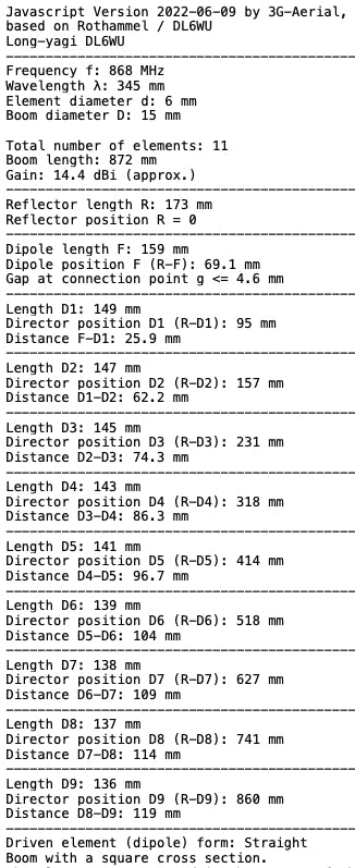
By the help of the on-line DL6WU calculator all the element sizes are as in the following pictures.
To make the antenna you need these items...
- 1m Aluminium boom, square, 15mm (15.84), 1.70 thick;
- 25cm Aluminium internal boom reinforcement, square, 11mm (11.46), 1.60 thick;
- 2m Aluminium tube, round, 6mm (6.12), 1.00mm thick;
- 20cm Copper tube, round, 6mm (6.06), 1.00 thick;
- 5.5cm Copper solid, round, 3mm;
- 5.5cm Aluminium solid, flat (to shape as "L" for SMA-F), 15mm x 2mm thick;
- 1 x SMA female panel connector;
- 1 x Capacitor, ceramic, variable 1-3pF 60-100V;
- 11 x M3x16 inox screws (for wood);
- 2 x M3x12 inox screws + washer (for wood);
- 2 x M3x7, plastic screws + nut;
- 22 x Gummy 5mm CW19-3 tube protectors (Leroy Merlin);
- 2 x 15mm plastic boom protectors;
- 10 x PETG plastic elements holders (see 3D files and PCBWay);
- 10 x PETG plastic screw covers (see 3D files and PCBWay);
- 1 x PETG plastic internal gamma-match support (see 3D files and PCBWay);
- 1 x PETG plastic external gamma-match support (see 3D files and PCBWay);
- 1 x PETG plastic gamma-match support cover (see 3D files and PCBWay);
- 1 x M6 Clamp, metal, 50mm distance, 2 plates (boom-mast support);
The dipole "F" is the active element of the antenna, it is responsable to generate/convert the electromagnetic field radio signal from/to an electric signal. The gamma-match makes the right marriage between the antenna and the cable connected to it adjusting the impedence (50 Ohm). It could be difficult to understand, from a DC or AC low frequency technician/hobbyist point of view, how the Radio Frequency RF signal is managed by a "shorted circuit" as the dipole + gamma-match look like. It has been hard for me too :-)
I suggest to watch this video on Youtube to better understand how it works. You will see interesting things, one of these is a different way to build the variable capacitor, in this project I used a "common" ceramic one instead.
The antenna is intended to be used for receiving, or transmitting low power radio signal as per Lo.Ra. specification (in Europe around 20mW as max at 868Mhz). If you need to transmit with more power you have to change the variable capacitor with a higher voltage rated one according with your needs. The capacitor I used is 63V rated and is fine for receiving and should be fine for transmitting 20mW of power too.
The length of the matching rod is intended to be 27.7mm long (see the above specification) but is better to make it longer (55.0mm in total) so we can change this value due to antenna construction differences and working frequency needs. We can change this value on the fly during fine tuning by the way of a "slider" the small copper part that connects the dipole "F" element to the matching rod; to temporary keep in place the slider between the two round elements you have to make on its both sides a concavity, so it will stay there letting you moving it to both sides right and left, so more outer or more inner from the theoretical 27.7mm point; after fine tuning you have to solder the slider.
The fine tuning is made connecting a NanoVNA S11 port instrument to the antenna already fixed to the mast, possibly at the final position, with a 2m long SMA-M SMA-M H155 cable. The NanoVNA must be calibrated for the needed frequency in the range 800-940Mhz and set Display/Format/SWR to watch SWR graph; look at Display/Scale the Top value should be set to 3 and the Bottom value to 1; move the display cursor Marker 1 to the desired center frequency (i.e. 868Mhz). Now you are ready to roughly tune the antenna: move the central cursor of the variable capacitor (possibly use a ceramic screwdriver for less interferences) to have a low SWR value; now manually move the gamma-match slider to have an even better SWR value; repeat again the operation with small changes to the capacitor and the slider to fine tuning. You could restrict the range on the display to focus the desired working frequency (i.e. 868Mhz) going to Stimulus/Start setting it value to 848Mhz, then go to Stimulus/Stop setting it to 888Mhz. The antenna is tuned when you reach at the Marker 1 or near it a low SWR value; a good value should be less than 1.5; the minimum value is 1.0 (but is quite hard or nearly impossible to reach 1.0 in reality).
The cable position, for the portion near the antenna, is important because it could influences the frequency response and the SWR; after connecting the cable to the antenna let it makes an arch avoiding to pass near the reflector element, then fix it with plastic straps in a stable way; this operation should be done before fine-tuning the antenna;
I took some screenshots of the FreeCAD software I used to project the gamma-match support, and the other plastic elements too.
I took some pictures of the real antenna I made so you may have a look at details of all parts and components.
- Cut the tubes by the way of a tube-cutter (pipe cutter), it is precise (do not use a saw or a grinder); I found a cheap one just for a few bucks;
- Put the inner boom reinforcement just the first 25cm where the clamp is; in case it is not stable because of the smaller size, put around some copper or aluminium adhesive foil;
- The inox screws (for wood) have to make its own tread while you screw-in the boom the first time; let choose the holes size accordingly (not too narrow, not too wide);
- After you fine-tuned the antenna remember to solder the gamma-match slider; I made an additional gamma-match plastic support, both internal and external parts, just to solder the copper elements: the heat of the solder probably will bend/burn these plastic parts during this session; after soldered put in the trash the additional temporary plastic support and use a new one to finally mount the gamma-match on the boom; the plastic support is made in two parts to facilitate this operation;
- All sizes and distances are precisely calculated and must be respected as precisely as you can using a caliber; it is recommended to do zero, or less than a millimeter, "errors" of dimensions;
- Make the plastic elements in PETG because this material is better for weather conditions and outdoor use. I used PLA for the first prototype but I passed immediately after to PETG (maybe I could paint them) made by the professional company PCBWay: they will print the parts for you for a reasonable price, I love them.
- Despite it is needed a very good precision, the aluminium and copper elements size aren't. They sell an aluminium square element as 15mm wide/high but in reality it is "around" 15.84mm, the same "precision" you may find about the tubes... But these small differences can be superseded by final fine-tuning with gamma-match (slider and variable capacitor);
- Do the fine-tuning with the help of a NanoVNA instrument to set SWR value as little as possible at/near the frequency you are going to use this antenna (i.e. 868Mhz); a good value should be less than 1.5; the minimum value is 1.0 (but is quite hard, or nearly impossible, to reach 1.0 in reality);
- It should avoid rain (as well as spiders and bugs) to enter the boom, all eleven elements and the gamma-match box where the variable capacitor and SMA connector are; put some small amount of sealant silicon for this purpose but remember the screws must electrically connect the elements (reflector, dipole and directors) with the boom; I used a syringe to do this carefully;
- Be sure to use "natural" aluminium for elements and boom: try with a tester if they are conductive on the surface; if not, probably they covered the surface with something chemically, not conductive, to protect the metal. You MUST REMOVE the protection on the surface around the screw holes to have elements and boom electrically in contact, use paper sand or a lime around that area (not all the surfaces).
- To keep together the two parts of gamma-match support let use plastic screws + nuts (not metal);
- To mark the holes position for all the elements, let start with the smaller front element one, 8mm from the front boom edge, so go backwards considering the respective distances values, ending with the reflector the longer one, then at the end the remaining 12cm boom space is available for the clamp mast support;
- Make the clamp holes according to the desired polarisation of the antenna, vertical or horizontal; if you need a vertical polarisation antenna like in this project, the holes have to be made from top to bottom so the antenna will be mounted on the mast 90° degrees comparing the clamp;
- The antenna is intended to be used for receiving, or transmitting low power radio signal as per Lo.Ra. specification (in Europe around 20mW at 868Mhz). If you need to transmit with more power you have to change the variable capacitor with a higher voltage rated one according with your needs;
- The cable you use to connect the antenna to your radio equipment or your SDR dongle should be a good cable with low loss parameters like the H155 or better/similar one. The UHF (Ultra High Frequencies) require a good cable, possibly the line should be less than 10m long, cabled with good connectors too as per SMA connectors. You should not use rg58 or rg174 or similar cables because they have high loss especially if the line is longer than a few meters.
- The cable position, for the portion near the antenna, is important because it could influences the frequency response and the SWR; after connecting the cable to the antenna let it makes an arch avoiding to pass near the reflector element, then fix it with plastic straps in a stable way; this operation should be done before fine-tuning of the antenna;
- Ones connected the cable to the antenna you should protect the SMA connector with a piece of heat shrinkable plastic tube;
- For receiving-only purposes I suggest to use a good preamplifier with included filter tuned at required frequency. I tested Uputronics (preamplifier+filter, all in one) but also Terra preamplifiers are considered good to be accompanied with an additional filter if needed. The preamplifier should be a must if you have a cable line longer than 10m and/or to receive much better than before. The Uputronics should be installed close to the antenna (less than 1-2m far) and can be powered by the way of the receiving cable line (H155) just enabling the Bias-tee of your SDR dongle, or installing a separated Bias-tee generator near your radio equipment to give the required 5Vdc power; I use Uputronics preamplifiers since many weeks 24/24h and I am very happy;
I did a performance test on the antenna using a NanoVNA instrument connecting at its S11 port a simple vertical portable omnidirectional antenna I knew it works fine at 868Mhz to transmit, by NanoVNA, a signal with range 800-940Mhz; I connected another good simple vertical portable omnidirectional antenna to the S21 port to receive the signal. I positioned the two antennas at a distance of 2m at the same high of 1.5m: reading the graph on the display I read at 868Mhz the value of -39.21dB. At this point I changed the 2nd antenna on S21 port with the Yagi 11 elements directional vertical antenna and I read at 868Mhz the value of -24.77dB.
A simple calculation (39.21 - 24.77 = 14.44) let me to reach the conclusion that the antenna is working very well with a gain of around 14dB as expected.
Even this time I decided to try the famous and popular PCBWay services. Some our beautiful project deserve a real professional service giving to them precise and superb items like PCB and 3D enclosure/component. I visited for the first time PCBWay website some months ago (http://www.pcbway.com) and after a few minutes I had been able to obtain the final price of the PCB just uploading the .ZIP Gerber file and setting some preferences of the board like colour: I choosen the blue but is still available the most popular green, or a shining white or red or others. They shown to me a preview of the board: impressive.
The same for the 3D printings (just uploading the. STEP or .STL file/s) and you cannot image how many materials are available: PLA, ABS, PETG, Resin, Polycarbonate but as well as Aluminium or Steel or... Titanium! What, Titanium?! It is incredible.
They offer other services actually I have not tried them yet but with these two I can say I am very satisfied. Shipping time were quick. The price was adequate.
Future of the Project:This Yagi antenna is very good as is but I am working to make another one, exactly the same as this one, to couple both two in a stack as one with even more final gain. It will involve a signal combiner (probably with some gain loss). We will see if it will make the effort worth the job, or, after all tests, I give up and let just the single antenna do the work.
News / Updates:03.02.2025 - the 3D printing files are available on my account at grabcad.com website too;


Comments