

Hardware components | ||||||
 |
| × | 1 | |||
| × | 1 | ||||
Software apps and online services | ||||||
| ||||||
Hand tools and fabrication machines | ||||||
 |
| |||||
this "T-Boom" project mainly is a "marriage" of other two:
- SoftRF on LilyGO T-Beam (https://github.com/moshe-braner/SoftRF/blob/master/README.md)
- SkyView on AMOLED 1.75" (https://github.com/slash-bit/SkyView-AMOLED-round-1.75-TFT_eSPI/blob/main/README.md)
My contribution is to put together these two projects to have a complete and rich handheld/portable device to use airborne on small aircrafts as per gliders, paragliders, hangliders, etc. The main work done is to make a second PCB the same size as the T-Beam connecting all original and optional peripherals:
- LilyGO T-Beam LoRa device with his original antenna and GPS; on it is installed the SoftRF firmware made by Moshe Braner; the device transmit and receive digital data information live to/from other similar devices (on aircrafts and base stations for tracking);
- LilyGO AMOLED 1.75" S3, a vibrant colour display with SkyView firmware installed, made by Slash-Bit; this display shows aircrafts around in a beautiful and brilliant way;
- New Li-Ion 3000mA/h battery as substitution of the original 18650 to have a lower profile;
- Oled 128x64 monochromatic display for reading SoftRF status all the time;
- Original GPS antenna mounted at 45° for a better reception even with the device placed horizontally or vertically;
- An active buzzer working at 3.3V and driven with a 2N2222 transistor for good acoustic alarms (collision awareness);
- An high brightness white LED as "strobe" light for personal visual alarms (collision awareness);
- GNS5892R module for ADS-B general aviation reception with an antenna tuned for 1090Mhz; digital data information are passed to SoftRF and integrated with the other;
- On/Off switch to mechanical cut off the battery when the device is not in use;
- BMP280 module as pressure altitude sensor;
Another great contribution in this project is the 3D printed box containing everything in an handheld reasonable size.
Completing the box are two light pipes to have a view to the internal status LEDs, and a lanyard to tie up the device on board.
as aviator pilot it is important on the air and on the ground to keep the "Safety First" in many aspects of the flight and pre-flight, one of these is avoiding collisions. Last few years even small aviation, free-flying aircrafts as per sailplanes, paragliders, hanggliders, etc., in future drones too, started to adopt instruments to see and let be seen to others. The sky will be crowd.
One cheap but effective instrument is the T-Beam model of LilyGo company (T-Echo as well). These LilyGo can be used installing various software, my favourite one is SoftRF version by M.Braner. SoftRF has been originally made by Linar Yusupov but some others decided to modify / improve his project.
How it Works:When you are airborne LilyGo T-Beam transmit and receive to/from other devices on flying aircrafts radio digital data containing informations regarding altitude, speed, direction, etc. ; is needed and very important that you and other aircrafts around using the same communication protocol or NO CORRECT or NO WARNINGS are exchanged!
If correct data is received and a possible collision is detected by LilyGo T-Beam, it transmits via bluetooth the information regarding the potential collision aircraft and alarm level. Data is transmitted in NMEA like format. The AMOLED SkyView display receives datas via Bluetooth-LE to show aircrafts around similar to a "radar"; for details see SkyView documentation; additionally to the radar view it has a compass view and a detailed aircraft data view; to change the view you may use either the long button or sweeping the screen with a finger side to side (up to down or vice versa to change zoom level.
We could have 3 alarm levels from T-Beam: 1=lower=easier=20" from the collision (1 bip), 2=medium=15" from the collision (2 bips), 3=higher=harder=10" or less to the collision (3 bips and "strobe" LED fast blinking). For details see SoftRF documentation. Even AMOLED provide a kind of visual warning on the display with a line and a circle around the aircraft. For details see SkyView documentation.
- Install SoftRF software (firmware) on T-Beam, install SkyView software (firmware) on AMOLED (instructions at github.com as per above links provided);
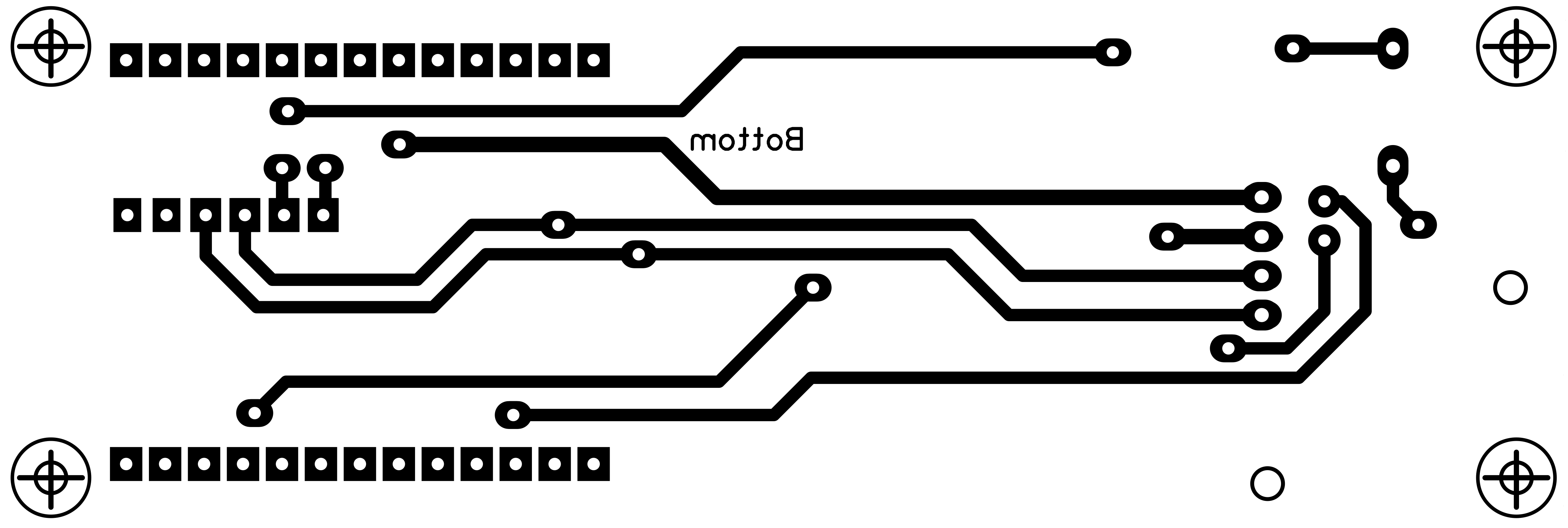
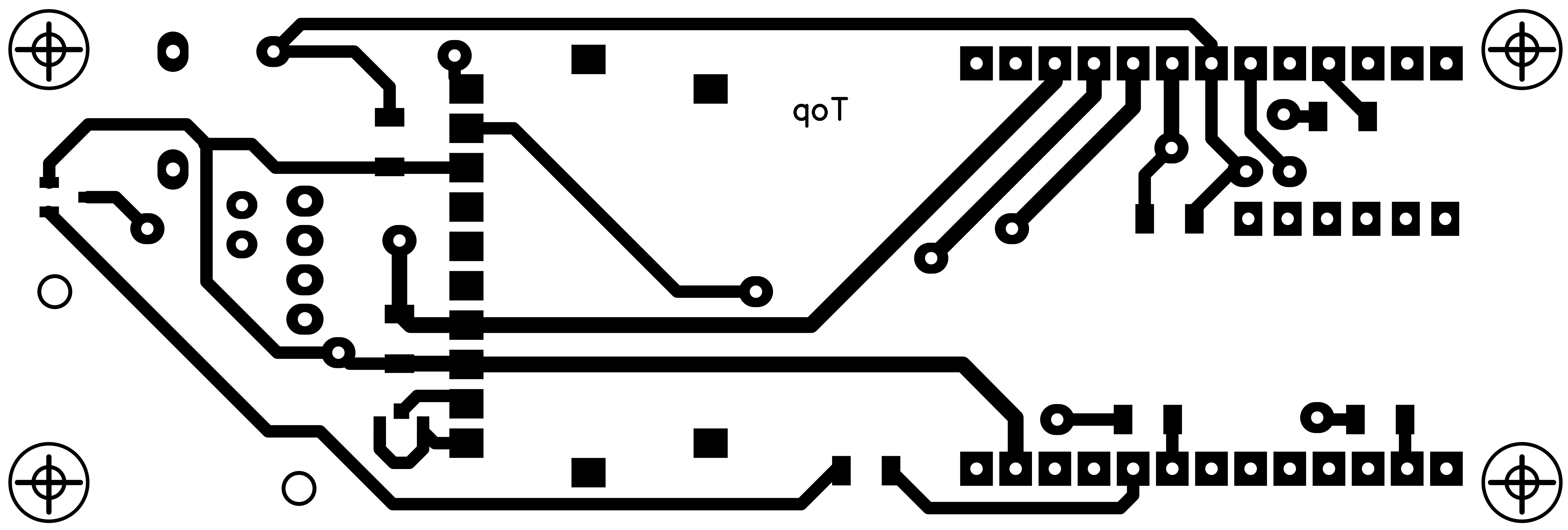
- Make the double layer PCB, your own or from a professional company;
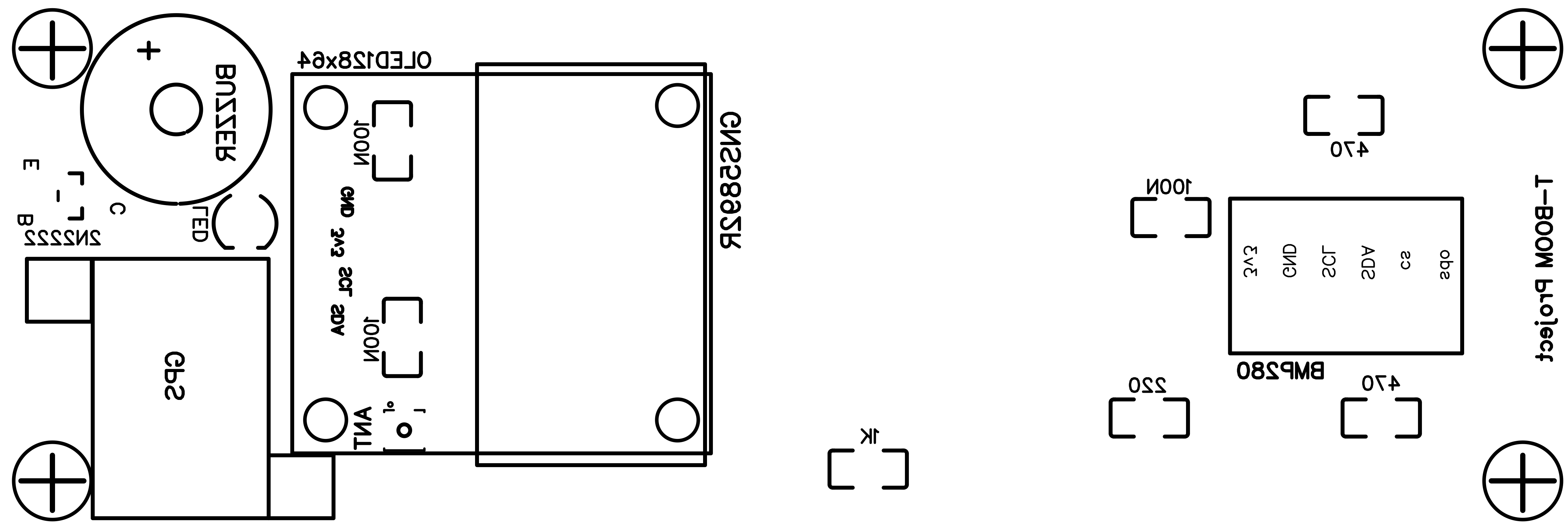
- Solder the copper rivets, the SMD components, IPEX, buzzer, 4PIN F strip and LED;
- Print all 3D components (9 items), then cure all their holes checking all parts will fit (screws, light pipes, switch, buttons, SMAs, USB, LED, Oled, AMOLED);
- Place and screw the GPS bed, 30° or 45° model;
- Stick some Kapton tape under BMP280 and ADS-B modules to avoid electrical contacts with PCB copper tracks;
- Solder BMP280 and ADS-B modules;
- Solder the M pin strip on the Oled, then remove the plastic support of the strip; cut approx. 2mm of the pins and round a bit their cutted side (they are too long);
- Screw the Oled on the top 3D part using M2 screws, nuts and washers;
- Place the top and middle-top 3D parts together, place the 3D long button and screw the AMOLED on (be carefully with the small screws);
- Unsolder and remove the original battery holder from T-Beam;
- Solder the two M/M gold pin strip on T-Beam;
- Put together T-Beam and the PCB using M/F 5mm M2 hexagonal spacers;
- Place the 3 x 3D short buttons and the 2 x light pipes;
- Insert the two circuits inside the 3D middle part and screw them with M/F 6mm M2 M2 hexagonal spacers;
- Solder the 2 x gold strip lines pins on the PCB (just the used ones);
- Screw the SMA connectors with external washers and nuts, place the GPS on the bed using double adhesive tape and a bit of hot glue on the side;
- Connect the antenna ADS-B pigtail IPEX connector on the PCB IPEX connector;
- Connect the ST-XH 1.25mm M connector + red/black wires 10cm to the AMOLED; pass the wires on the left side of the PCBs and solder them on (+) and (-) battery T-Beam spots (or equivalent places);
- Insert the mini-switch and solder it with the wires from battery F connector and the ones from the T-Beam battery spots in a manner to cut off the red (+) of the battery when off; the black (-) wires has to be connected all the time;
- Stick some Kapton tape to hold the wires on the back of T-Beam; a thin sheet of foam should be placed to protect the battery from the soldered gold strip line pins;
- Screw the M2 10mm F/F hexagonal spacers on the back of the T-Beam, connect the JST battery connector (CHECK the correct (+) and (-) wires!), screw the 3D bottom part with plastic screws;
- Put the top 3D parts on the 3D middle part paying attention to the 4 pins of the Oled and the LED they have to be in place gently; screw with the last 4 x M2 plastic screws;
- Screw-on both the LoRa (left) and ADS-B (right) antennas;
Switching ON the device the T-Beam Oled display will show his information datas, the buzzer will produce some bips, the LED will blink, the AMOLED will show as well his information datas. During GPS receiving process the blue LED (see trough the left light pipe) is blinking when no fix, still blue when fix; the red LED (see trough the right light pipe) is off when no fix, blinking 1 pps when fix.
As per T-Beam (SoftRF) and AMOLED (SkyView) project websites on github.com (see the above links provided), you have to customize the setup one at a time by the way of the WiFi connections and IP=192.168.1.1.
To recharge the battery you have to leave the switch to on position, connect the mini-USB to power, push the relative buttons to off both T-Beam and AMOLED. During charging process the blue LED (see trough the left light pipe) is still on, when charged is off.
- 2 x SMD 1206 resistors 470 Ohm
- 1 x SMD 1206 resistor 220 Ohm
- 1 x SMD 1206 resistor 1K Ohm
- 3 x SMD 1206 capacitor 100nF
- 2N2222 SMD SOT-23-3 transistor
- IPEX SMD antenna M connector (ADS-B )
- SMA-F panel connector + pigtail coax cable + IPEX antenna F connector (ADS-B)
- GNS5892R module for ADS-B reception (GNS Electronics GmbH)
- Antenna SMA-M 1090Mhz (45mm long or similar) for ADS-B reception
- BMP280 pressure sensor module, I2C
- OLED 128x64 monochromatic, I2C, (attention to the power PIN position!!!)
- Active buzzer 3.3V
- White LED 3mm high brightness/efficiency (5000mcd or more)
- 2 x 13pin strip line gold plated, double M
- 4 pin strip line M + F (OLED)
- Mini switch on/off
- LilyGO T-Display AMOLED 1.75" ESP-32 S3
- JST-XH 1.25mm M connector + red/black wires 10cm (for AMOLED power)
- JST-PH 2.0mm F connector + red/black wires 10cm (for battery to switch power)
- LilyGO T-Beam v1.2 LoRa ESP32 SX1262 (with remote SMA 868Mhz antenna, with remote GPS IPEX NEO M8N antenna)
- Li-Ion 3.7V 3000mA/h battery
- PCB double layer 33x100mm
- Some plastic M2 screws, washers, nuts and hexagonal spacers
- 2 x mini screws for T-Display
- 2 x LC3-1 light pipes (4.2mm diameter, 5mm long, or similar)
- 14 x copper 0.8mm mini rivets (for PCB vias)
- 3D printed GPS bed, 26° model for new 12x12mm antenna, or 45° model for original 6x16mm antenna
- 3D printed top layer box
- 3D printed middle-top layer box
- 3D printed middle layer box
- 3D printed bottom layer box
- 3D printed 3 x short buttons
- 3D printed 1 x long button
- 45cm long lanyard (diameter 1.4mm)
- Some Velcro M for the bottom
- Some Kapton tape for insulation
A few moths ago I buy a bunch of 868Mhz small antennas. I "sacrificed" one: pulling away the rubber black cover it shows the core (coil) wire forming the antenna. I guess it is a 1/4 wave length, resonating at 880Mhz as per Nano VNA test. At 880Mhz the wave length is 0.34067m, so 1/4 is 0.0852m (85.2mm). At 1090Mhz the wave length is 0.27504m, so 1/4 is 0.0688m (68.8mm). The difference is 16.4mm shorter in favour of a 1090Mhz resonant antenna. To cut the wire is easy, and after putting at his place the rubber black cover I obtained an ADS-B small antenna working at 1090Mhz better than the original that was made for a lower frequency. Honestly I proceeded cutting the wire just a few millimeters at a time, wear the rubber cover, testing with Nano VNA, cutting again... etc. etc. until I reached a good SWR at 1090Mhz. I suggest to do the same instead to cut directly the theoretics 16.4mm. The rubber cover influences the response as well, so is needed to put it at his place before testing with the instrument. I stick a white piece of tape to recognise the cutted 1090Mhz antenna.
Pictures of the modified antenna:It is a bit of work to program and make everything together but at the end you will have an handheld device you will appreciate and use airborne with satisfaction.
A big thanks to the Authors of the two projects I put together! We look forward to have even more and precise features for these projects!
Happy landings!
News / Updates:- 09.09.2025 - 3D printing models: I just published even on GrabCAD website the 3D parts you may print for this project.
- 09.09.2025 - New 12x12mm GPS Antenna: I just ordered an antenna for replacing the original one to have a better reception, less time for a fix, specially during initial power-on. I already have provided a new GPS bed (26°) to replace the previous one (45°), it should fit. We will see...


Comments