


Hardware components | ||||||
| × | 1 | ||||
| × | 1 | ||||
| × | 1 | ||||
 |
| × | 1 | |||
_ztBMuBhMHo.jpg?auto=compress%2Cformat&w=48&h=48&fit=fill&bg=ffffff) |
| × | 1 | |||
 |
| × | 1 | |||
Software apps and online services | ||||||
 |
| |||||
I've recently posted a tutorial about this project on YouTube explaining everything you can read on this article. You can watch it right below.
IntroductionPotentiometers are one of the most common input devices you’ll find in electronics projects. They’re often used to control things like audio volume, screen brightness, or even robot speed.
In this tutorial, part of the Arduino for Beginners, 24-lesson series, we’ll learn how potentiometers work, how to connect them to an Arduino, and how to use one to control an RGB LED.
By the end, you’ll not only understand potentiometers, but also gain hands-on experience using them to interact with your Arduino.
How Potentiometers WorkBack in lesson #4, we learned about resistors: components that provide a fixed resistance. A potentiometer is very similar, but instead of one fixed resistance, it lets you vary the resistance by turning a knob.
If you look closely at a potentiometer, you’ll see it has three pins:
- Pin 1 - usually connected to VCC (positive voltage)
- Pin 2 (middle pin) - called the wiper, this is the one that outputs a voltage based on the knob position
- Pin 3 - usually connected to GND (ground)
Inside the potentiometer, the wiper slides along a resistive track (see the third image). When you turn the knob:
- One end of the track is at 0 volts (GND).
- The other end is at the supply voltage (for example, 5V).
- The wiper gives you any voltage between 0V and 5V, depending on the knob’s position.
One important detail: potentiometers have a maximum resistance value, usually printed or stamped on their body, for example, 5kΩ (5, 000 ohms).
This means that when the knob is turned all the way to one side, the resistance reaches that maximum. As you rotate it, the resistance decreases until it reaches nearly zero at the other end.
This is what makes potentiometers so useful. Instead of reading just ON or OFF, your Arduino can measure a range of values using the analogRead() function - as this little component works as a voltage divider.
SponsorBefore we jump into the project, I would like to talk about the sponsor of this lesson: DFRobot. This company provided me with the MindPlus Arduino Coding Kit, a kit that has everything a beginner needs to take the first steps into Arduino. This is also the kit I will be using in every lesson of this 24-part series.
The MindPlus kit includes an Arduino-compatible board, an I/O expansion shield, a variety of sensor and module boards (like the RGB LED and potentiometer we use here), jumper cables, and clear documentation.
I chose to work with this kit because the components are beginner-friendly, well labeled, and they just work together pretty well, which makes following along much easier.
If you want to follow the lessons exactly as shown, grab the same kit. You’ll get the parts used in every project and save time hunting for compatible modules.
Big thanks to DFRobot for supporting this series and making it simpler for beginners to start learning electronics.
Alright, let’s put the potentiometer to work.
In today’s project, we’ll use it to control the color of an RGB LED. Here’s the idea:
- If you turn the knob a little, the LED will turn red.
- Turn it more, and the LED will switch to green.
- Turn it to the far end, and it will switch to blue.
It’s like using the potentiometer as a color selector switch.
I know we’ve been doing a lot of LED projects, but trust me, this one is worth it - and soon we’ll move on to more advanced modules.
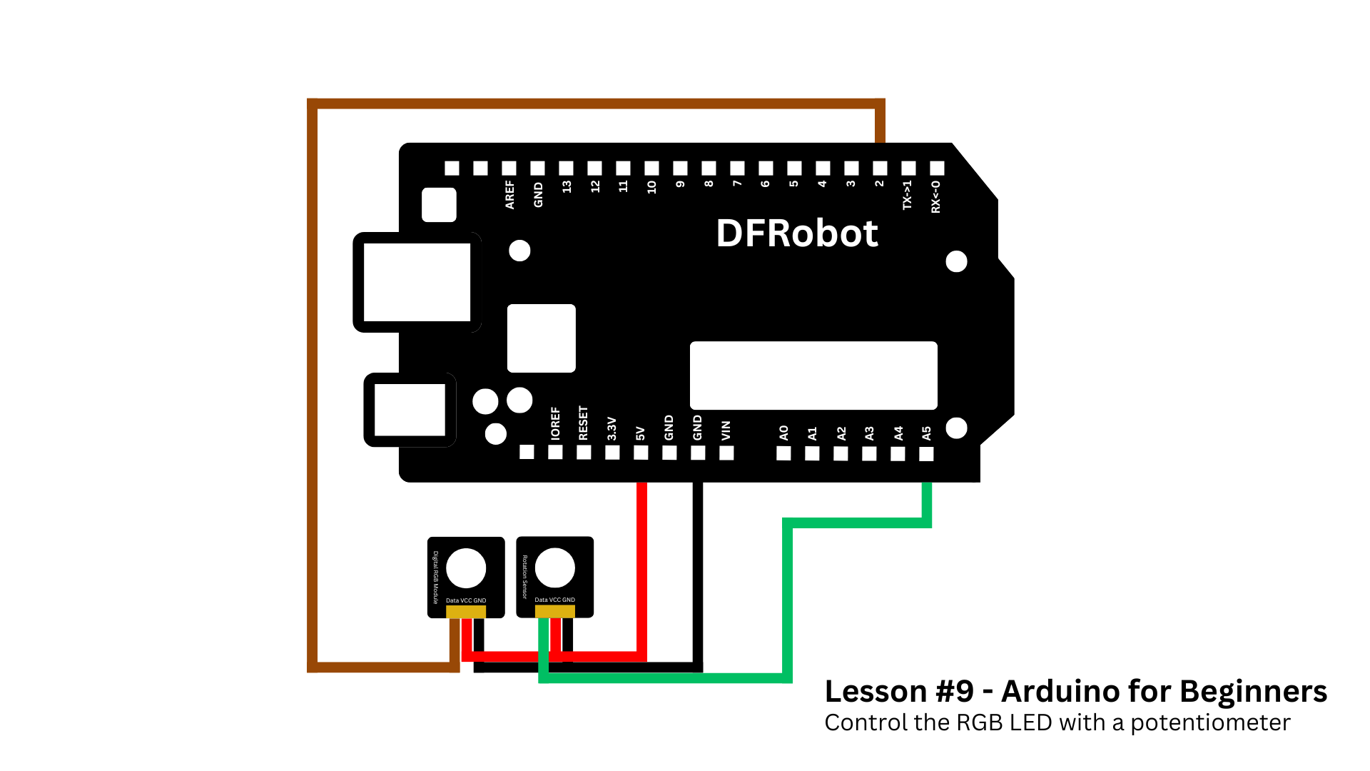
After you grab all components (the list of materials is in the beginning of this article), assembly is simple:
- Place the I/O expansion shield on top of your Arduino.
- Connect the RGB LED module to port 2.
- Connect the potentiometer to port A5.
That’s it. If you prefer, you can also check the wiring diagram below to make sure everything is correct.
As I told you before, the potentiometer acts like a selector switch:
- Turn it a little and gets red.
- Turn it more to turn on the green light.
- And turn it further to activate the blue LED.
And of course, when you rotate it back, it goes back through the colors.
Now let’s take a look at the code. You can find the full version in the GitHub repository of this course. So go ahead and copy and paste it in your Arduino IDE.
In the first part we definied variables as well as start the communication with the RGB module, using the NeoPixel library.
#include <Adafruit_NeoPixel.h>

#define RGB_PIN 2
#define NUMPIXELS 1
#define POT_PIN A5

Adafruit_NeoPixel pixels(NUMPIXELS, RGB_PIN, NEO_GRB + NEO_KHZ800);

void setup() {
    pixels.begin();
    pixels.clear();
    pixels.show();
}
Inside the loop function, we read the potentiometer position. This gives us a number between 0 and 1023 - with 0 meaning no voltage and 1023 meaning 5V.
In this case, if you turn the rotation sensor all the way left, it gets near 0. Turn it all the way right, and it gets 1023.
int potValue = analogRead(POT_PIN);Sometimes even when the knob is fully left, the reading doesn’t land exactly on zero. That’s why we create a threshold. If the value is less than 50, we just turn the LED off and exit the loop. This makes the "off" position more reliable.
if (potValue < 50) {
    pixels.clear();
    pixels.show();
    return;
}
After that, we use the map() function. The map function is like a translator - it takes a number from one range and converts it to another.
In this case, we map the potentiometer range (50 - 1023) into three sections: 0, 1, or 2.
Depending on which section we’re in, we set the LED to red, green, or blue.
int section = map(potValue, 50, 1023, 0, 3);

if (section == 0) {
    setColor(255, 0, 0);   // RED
} else if (section == 1) {
    setColor(0, 255, 0);   // GREEN
} else {
    setColor(0, 0, 255);   // BLUE
}
The setColor() helper function updates the color of the LED according to the potentiometer output.
void setColor(int r, int g, int b) {
    pixels.setPixelColor(0, pixels.Color(r, g, b));
    pixels.show();
}
This is just the beginning of what you can do with potentiometers. Instead of switching colors, you could:
- Smoothly fade between them.
- Control the brightness of a single LED.
- Adjust the speed of a motor.
- Change the pitch of a buzzer.
The potentiometer is a great example of how analog inputs open up endless creative possibilities.
ConclusionThis was lesson #9 of the Arduino for Beginners series.
In lesson #10, we’ll move on to light sensors - a crucial concept for our first big project coming up in lesson #13.
Thanks again to DFRobot for providing the MindPlus Arduino Coding Kit and supporting this series.
Happy making, and see you in the next project!


Comments