

Hardware components | ||||||
| × | 1 | ||||
| × | 1 | ||||
 |
| × | 1 | |||
Software apps and online services | ||||||
| ||||||
| ||||||
While I was studying university, I built a robot called LGDXRobot that collecting and sorting rubbish for recycling. It was based on the Nvidia Jetson Nano using ROS Melodic and detecting objects using the jetson-inference framework.
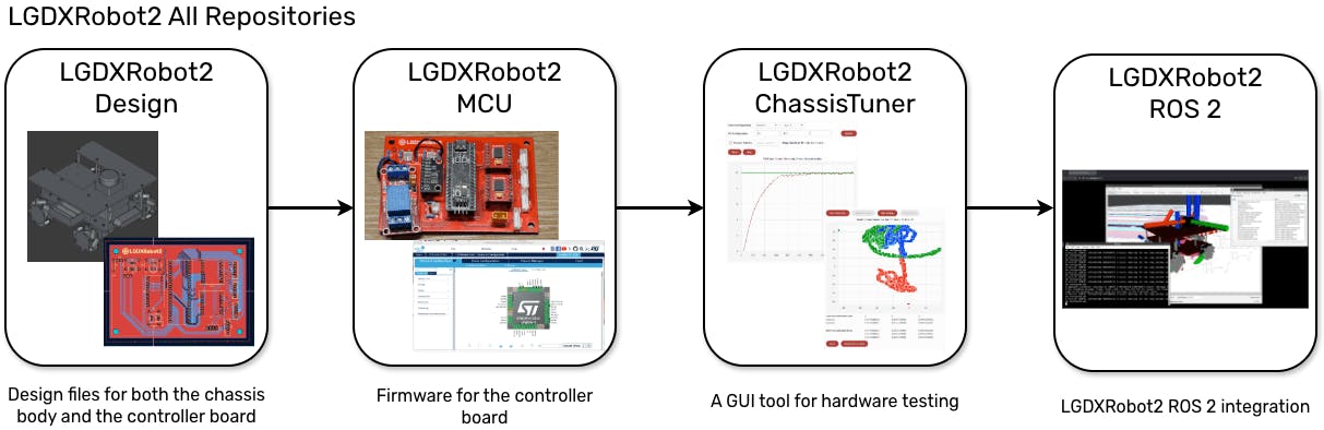
After graduating, I redesigned it as a universal robot and adopted ROS 2, which eventually became LGDXRobot2. It is a mobile robot equipped with four Mecanum wheels, LiDAR, a 9-DOF IMU, and wheel odometry, making it suitable for navigation tasks. LGDXRobot2 has following features:
Open-Source and Reproducible Hardware Design
LGDXRobot2 provides open-source designs for the chassis body, controller board circuit, and software source code. It includes both the design files and manufacturing files which is ready for reproduction.
GUI Hardware Testing Tool
ChassisTuner is a GUI tool specifically designed for LGDXRobot2. It includes hardware testing, PID tuning, and IMU calibration with real-time visualisation.
ROS 2 Support
LGDXRobot2 fully supports ROS 2. It is not just a ROS node that connects to the hardware. It also includes a URDF model for RViz visualisation, remote control via the joy node, navigation with Nav2, and simulation in Webots.
The packages include launch files to run Nav2 examples and support switching between pre-tuned parameters to test different configurations.
Easy Installation
The LGDXRobot2 ROS 2 packages are easy to install via APT on Ubuntu. It also has ready-to-use Docker images with a remote web interface. These installation options support both AMD64 and ARM64 computers. With CI/CD pipeline support, the packages are always kept up to date.
Demonstration Videos
These videos were taken using an older design of LGDXRobot2.
Chassis
The chassis is about 240 mm in width and length, with a height of 134 mm (depending on the wheels and without LiDAR). It is designed to maximise the use of available space in a three-layer chassis structure.
System
The system has a two-layer control system. The first layer is a STM32 BlackPill based controller board responsible for real-time motor control, PID regulation, and sensor data acquisition.
The second layer is an onboard computer running high-level applications such as ROS 2 and Nav2. Which can be a Jetson, Raspberry Pi, or NUC.
The power supply is isolated between the motors and the logic circuits.
The BOM for the robot is quite long, so the complete list can be found here.
For the LGDXRobot2 chassis plates, they can be manufactured by laser-cutting acrylic sheets. The files can be found here. Simply send them to a laser-cutting service and specify a thickness of 4 mm for the plates.
For the controller board, it can be manufactured by any PCB manufacturer. The files can be found here. Zip them and send them to the manufacturer. Ensure that the board is fabricated as a two-layer PCB.
After preparing all the materials, here are the instructions for assembling the robot.
Flashing Firmware to the Controller BoardThe controller board requires firmware to control the hardware. The pre-compiled firmware can be obtained here. Flash the firmware using STM32CubeProgrammer.
When starting the robot, it must be placed statically on a flat surface, as it needs to calibrate the IMU. After three seconds, a clicking sound will be heard from the relay and the red LED will turn off.
If the red LED does not turn off, it means the robot is in the emergency state. This is a safety mechanism to protect both the robot and people. There are three types of Emergency Stop:
- Software Emergency Stop: A software feature that prevents the robot from moving. It can be enabled by sending a command to the controller board.
- Hardware Emergency Stop: A physical button connected to the motor circuit and the voltage divider circuit. When triggered, the power is redirected to the voltage divider circuit, which activates the emergency stop.
- Battery-Low Emergency Stop: The motor power source is connected to the voltage divider circuit. The controller board monitors the voltage and stops the robot if it drops below 12 V.
LGDXRobot2 features PID control for the motors and uses an IMU for sensor fusion. These require tuning and calibration. With ChassisTuner, this can be done through a GUI tool and saved directly to the controller board without modifying the code or re-flashing the firmware.
To use the tool on Ubuntu 24.04, the following dependencies need to be installed:
sudo apt install libxkbcommon-x11-0 libxcb-cursor0 libxcb-icccm4 libxcb-keysyms1Then you can then download the tool here.
Connecting the Robot
Connect to the controller board using USB, then launch ChassisTuner. The device should be listed in the top-right dropdown menu; if not, press Refresh. After selecting the correct device, press Connect.
The connection status should display Connected. Try rotating the wheels to see the data change.
PID Turning
The PID Tuning tab allows fine-tuning of the PID constants for each motor to achieve the desired performance. Switch to the PID Tuning tab to view the PID parameters. If they are not visible, press Refresh.
Please ensure the robot is lifted when sending commands; otherwise, it may move and cause damage.
1. Motors Maximum Speed
The maximum speed defines the upper limit used by the PID controller when calculating output. To obtain the maximum speed, press the Auto Config button to automatically measure the maximum speed for each motor.
2. PID Configuration
LGDXRobot2 supports three different PID settings for various speeds. Level 1 is expected to be the lowest, and Level 3 the highest.
To select the configuration for tuning, choose the motor number and the level, then input the PID constants. Press Update, then press Send. The motor will start spinning and the chart will update accordingly.
When adjusting the PID constants, try increasing P by 1, I by 10, and D by 0.1.
Magnetometer Calibration
LGDXRobot2 supports the ICM-20948 sensor; the magnetometer requires manual calibration. Switch to the Magnetometer Calibration tab to view the calibration parameters.
To calibrate the magnetometer, scroll down and press Start Calibration, then rotate the controller board. When calibration is complete, press Send Hard Iron Only.
Soft iron calibration is currently under development.
Save Configuration
Switch to the Save Configuration tab, then press Save Configuration. The configuration will be saved to the controller board until a full chip erase is performed.
ROS 2 Packages Installation and ExamplesThe robot hardware is now ready to run ROS 2. There are two installation methods for ROS 2 support on LGDXRobot2, and both methods support AMD64 and ARM64 devices.
APT on Ubuntu 24.04
This method is design for Ubuntu 24.04 and have ROS 2 Jazzy installed
1. The packages are hosted in a self-hosted repository, install this package to add the repository and the public key.
wget -q http://packages.lgdxrobot.uk/lgdxrobot-apt-source.deb
sudo dpkg -i lgdxrobot-apt-source.deb
sudo apt update
2. Install the packages. This will also install the required dependencies, including the Nav2 stack.
sudo apt install lgdxrobot2-udev \
  ros-${ROS_DISTRO}-sllidar-ros2 \
  ros-${ROS_DISTRO}-lgdxrobot2-* \
  ros-${ROS_DISTRO}-lgdxrobot-cloud*
Docker
If you are using another version of Ubuntu or Debian, you can install the ROS 2 packages using Docker.
1. To allow access to hardware devices without root permissions, the lgdxrobot2-udev package needs to be installed. The package can be obtained from here, install it on the host machine (not inside the container).
2. Start the Docker image
docker run -d \
  --name lgdxrobot2 \
  -e PUID=1000 \
  -e PGID=1000 \
  -v /dev:/dev \
  --device-cgroup-rule='c 188:* rwm' \
  --device-cgroup-rule='c 166:* rwm' \
  --device-cgroup-rule='c 13:* rwm' \
  -p 3000:3000 \
  -p 3001:3001 \
  yukaitung/lgdxrobot2-desktop:latest
The desktop images include ROS2 GUI tools and provide a web interface suitable for remote control. After the container is started, the web interface becomes accessible at http://localhost:3000. For external access, the address https://<host-ip>:3001 should be used.
Hardware Testing
To test the hardware with ROS 2, run the command below, then spin the wheels to observe the changes in RViz.
ros2 launch lgdxrobot2_bringup bringup.launch.py \
  use_rviz:=True
Nav2 Navigation
To start mapping using Nav2, run the command below. You can then send a goal in RViz to move the robot.
ros2 launch lgdxrobot2_bringup nav.launch.py \
  slam:=True \
  profile:='slam' \
  use_rviz:=True
Then run the command below to use localisation mode with a saved map.
ros2 launch lgdxrobot2_bringup nav.launch.py \
  map:=<Absolute path to the map yaml file> \
  use_rviz:=True
The default Nav2 plugin is the DWB Controller, but you can change the profile to use other plugins:
ros2 launch lgdxrobot2_bringup nav.launch.py \
  map:=<Absolute path to the map yaml file> \
  use_rviz:=True \
  profile:='loc-mppi'
For other plugins:
- DWB Controller – This is the default plugin, so specifying a profile is not required.
- Model Predictive Path Integral Controller (MPPI) – Use loc-mppi as the profile name.
- Graceful Controller – Use loc-gc as the profile name.
- Regulated Pure Pursuit Controller – Use loc-rpp as the profile name.


Comments