


Hardware components | ||||||
 |
| × | 1 | |||
| × | 2 | ||||
| × | 2 | ||||
 |
| × | 1 | |||
| × | 1 | ||||
_wzec989qrF.jpg?auto=compress%2Cformat&w=48&h=48&fit=fill&bg=ffffff) |
| × | 1 | |||
| × | 1 | ||||
 |
| × | 1 | |||
 |
| × | 1 | |||
Software apps and online services | ||||||
| ||||||
| ||||||
 |
| |||||
| ||||||
| ||||||
Hand tools and fabrication machines | ||||||
 |
| |||||
 |
| |||||
| ||||||
 |
| |||||
 |
| |||||
Beyond their military impact, landmines pose a significant threat to civilians worldwide, particularly in regions like Iraq, Afghanistan, Sudan, Syria and Cambodia, where Cold War-era mines persist. Despite a global ban in 1977, these mines continue to cause harm, highlighting the need for accessible detection and disposal solutions.
The project targets the detection and marking of landmines due to their prevalence and high explosive contents. Addressing this class of landmines could significantly reduce casualties and improve demining efforts globally.
Advancements in autonomous technology, such as cheaper and more capable rovers equipped with detection and marking systems, offer promise for tackling this dangerous task. These autonomous systems can navigate minefields without risking human lives, presenting a viable solution to the ongoing threat of landmines.
Impact of Landminesz⚠️
Landmines pose a significant danger to civilians worldwide, often remaining buried even after conflicts end. Non-state actors, like terrorist groups, deploy mines without adhering to international regulations, leading to casualties and long-term consequences for survivors and their communities. Despite efforts to develop safe and affordable detection and cleanup methods, many areas affected by mines lack funds and skilled personnel, relying on risky approaches that endanger human lives.
The aftermath of conflicts sees many minefields left untouched, remaining active for years and causing casualties among civilians. The majority of victims are civilians, facing life-altering injuries that often result in permanent disability and dependency on community support. The impact extends beyond physical harm, affecting mental well-being and socioeconomic stability.
The Ottawa Treaty of 1997 aims to address the landmine issue by prohibiting their use, production, and stockpiling. However, it does not cover anti-vehicle mines, which remain a concern. While 162 states have signed the treaty, major military powers like China, Russia, and the United States have not, highlighting challenges in global efforts to address the landmine threat.
Detection Methodologies 👀
Detection is the most dangerous part of the de-mining operation, as it places the personnel who must detect the landmines in unknown danger. Landmines are designed to avoid detection and some have anti-tampering sensors, which makes any attempts to detect and disarm the mine more dangerous.
1) Prodding
The most accessible and cost-effective approach to mine detection involves physically probing the ground with specialized tools known as prodders. These tools typically consist of rigid metal sticks, approximately 25cm in length, often equipped with blast-resistant guards to shield the deminer's hand. However, this method is both hazardous and time-consuming. Deminers face significant risks as they have minimal distance from potential explosives, and each probing action covers a small detection area, requiring cautious handling as if encountering a live landmine
2) Metal Detectors
Metal detectors are another widely utilized tool for landmine detection. They provide a broader search area, and handheld versions offer greater standoff distance compared to prodders, allowing for faster and more extensive land coverage. However, metal detectors face challenges as many mines are designed with minimal metal content to evade detection. Consequently, the sensitivity of metal detectors must be finely tuned, leading to a high false positive rate where numerous non-threatening objects trigger alarms. This can significantly slow down the removal process, with false positives sometimes exceeding 1000 per landmine detection. There are alternative types of metal detectors with lower false positive rates and even some capability to identify the type of landmine, although these are less common. Typically, metal detectors are employed to expedite the prodding process by identifying search sites rather than probing every inch of land.
3) Ground Penetrating RadarsGround Penetrating Radar (GPR) represents a significant advancement in landmine detection by utilizing radar pulses to map subsurface areas. As radar waves penetrate the ground, they interact differently with various materials. By analyzing the strength of the reflected waves, GPR can determine the depth and composition of underground objects, potentially identifying landmines and their types. While GPR offers precise and reliable detection capabilities, it has its challenges. Interpreting the data returned by the sensor is complex and typically requires skilled operators to ensure effectiveness. Although progress has been made in computer processing of GPR data, it demands substantial computing power, often necessitating offsite servers or vehicle-mounted computer racks for real-time analysis. Additionally, GPR consumes significant power during operation, limiting its operational duration, which is a concern, particularly in environments where power resources are scarce, such as on robots or in rural and underdeveloped areas affected by landmine contamination. Moreover, GPR performance is highly influenced by the type of surface being surveyed, necessitating calibration for different soil types. It is particularly sensitive to soil with high conductivity levels, which can impact its performance.
Proposed SolutionThe proposed solution is to build an autonomous robot that can accurately find the mine's location using an ML model and give the response back to the control station
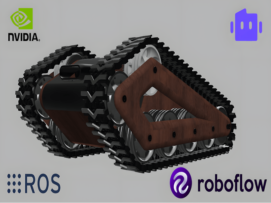
Rover Chassis Design and Manufacturing 🦾
For this rover we have planned a tank like structure, it is because it have to travel in different terrain and have to climb hills and valleys easily.
We have design the rover in S0LIDWORKS. From the design we were look into the manufacturability and complete the design.
Track MechanismIn our track design, the initial implementation failed. The design caused slipping while driving the motor, poor meshing, and high noise due to the lack of proper meshing. To address this, we explored different methods and finalized a new approach for the track motion. We combined the inner part of a bike chain with a 3D-printed part. The 3D-printed component formed the outer part of the bike chain and the track. We used a rod to connect these two parts. With this new design, the track worked perfectly, eliminating noise and slipping."
We have plan to use
- 3D Printer
- Laser Cutting Machine
- CNC Machine
With the 3d printer we plan to manufacture track(Using PLA+), track rubber padding (Using TPU), Front camera mount, Wheel, Wheel axil and motor mount.
For 3D printing we have convert all our part file into STL file format, slice the model in Ultimater Cura and finally we print all this in Ultimaker 2+ and Prusa mk3s+.
In laser cutter we cut the bottom cover top cover and middle support and front lower part. For laser cutting we have convert all the drawing file into Dxf File format and use Coral for Generating the G code file.
Using CNC milling machine we machined the wheel mounting and supporting part.
The idea behind choosing wood as the part material is mainly to reduce the over all weight and to try new machining aspects. We used artocarpus hirsutus wood as it has a high weight to strength ratio and also its cheap and easily machinable. One of the greater advantage in CNC Milling is that we can effectively reduce the machining while comparing with 3D printing.
Machine specification: Shopbot D2148
- Diameter: 0.25"
- Pass depth: 0.5"
- Spindle speed: 18000 rpm
- Feed rate: 1.125 inches/sec
- cutting volume: 24" x 18" x 3.5" 23" x 17" x 8" (with lower deck option)
Disclaimer: There are many safety issues related to this machining process. The spindle is rotating at a speed of around 18000 rpm and if the tool is not firmly tightened, it can cause serious injuries. Also, the workpiece has to be firmly fixed to the bed without any single movement in any direction. Another thing to make sure is that the work has to be within the milling limit. Proper removal of wooden swarf has to be ensured and proper lubrication has to be done at regular intervals. While choosing the work piece, make sure to consider the tolerances that have to be given for shaping processes.
In terms of the processes involved in this particular machining, facing and milling. The primary step is the preparation of the workpiece. Wood that is newly brought will have many irregularities and slight bends. So, primarily, it is necessary to smooth its surface and have to face both sides to have a clean plane without bending. Now the work piece is ready for machining.
Machine codes are generated using the integrated cloud software Autodesk Fusion 360. The design made in design mode is directly moved to manufacturing mode in Fusion 360. Then a new step is made. In that new setup, machine is specified, machining area is defined, the axes are defined and the body to be machined is also selected. Then, in that new setup, we are to define specific types of milling for each feature. For milling the outer boarder and full depth slots, 2D contour is chosen and for milling pockets we chose 2D pocket. Like such there are several options for specific structure. One the main advantage in using Fusion 360 is that its very much user friendly and have many fascinating features.
Working of Shopbot
While choosing each option for specific features, we have to specific the which tool is using for that operation, overall depth of cut, depth of cut in each path, tool movement height etc. After inputting all the required data, the software itself shows the path of tool and depth of cutting. We can edit the each parameters as per out requirement. Once everything done we can stimulate the milling process and can verify it. Then next thing is to post the process meaning to import the code. Once the code is generated, we feed it to the shopbot software for milling.
We have to fix the tool to the collet. Then the origin have to be set as per we defined in the fusion. The Z axis has also to be setup using the metallic plate. Then the spindle has to be jogged around the workpiece to ensure that the work is within the limit. After setting up all these things, we are to cut the part. The cut command is given and it will start to cut.
Tools used:
- Flat-end mill
- Ball end mill
- Face mill
Hardware Design, Selection And Components Testing ✅
For to make the rover Autonomous we were using ROS (Robotic Operating system) In Jetson Orin Nano.
JetsonOrin Nano
Drive(Motor)
For Robot traction we are using a Geared DC motor from Robokits, Which can produce 25KGCM at 100RPM With 12V supply.
From the datasheet we get the maximum current that going to consume at maximum load, we can use this in further calculation for battery.
For more details about the motor go to the datasheet.
Motor Driver
In motor driver selection we have tried 2 different motor driver, from that we finally fix CYTRON DUAL DC MOTOR DRIVER 5V-30V 10AMP - MDD10A.
Initially we have tried with a UART driver but at the time of testing it show a littile bit time delay in the data transmission so we switch to NMOS H-Bridge motor Driver and the feedback directly given to the Serial Node.
For more details visit the datasheet.
For Arduino library support click here.
RosSerial Node (Microcontroller)
We were using Arduino mega as a serial node for actuator control of our rover, This node will be acting as a bridge between motor driver and Jetson.
Setting up Jetson Orin Nano
Now wireup all the connection along with power supply and a display.
JetPack 6 doesn't work for us and and we go with the previous version JetPack 5.1.3. It work properly for us.
Now we can test each and every components.
For that we initially try to count the tick value from the encoder. We wire up motor with the Arduino Mega
Connections are:
HALL_A -> D2
HALL_B -> D4
VCC -> 5V (VCC)
GND ->GND
Then upload the code below.
#define ENC_IN_hall_A 2
#define ENC_IN_hall_B 4
boolean Direction = true;
const int encoder_minimum = -32768;
const int encoder_maximum = 32767;
volatile int wheel_tick_count = 0;
int interval = 1000;
long previousMillis = 0;
long currentMillis = 0;

void setup() {
  Serial.begin(9600);
  pinMode(ENC_IN_hall_A , INPUT_PULLUP);
  pinMode(ENC_IN_hall_B , INPUT);
  attachInterrupt(digitalPinToInterrupt(ENC_IN_hall_A), wheel_tick, RISING);
}
void loop() {

  currentMillis = millis();
  if (currentMillis - previousMillis > interval) {
    previousMillis = currentMillis;
    Serial.println("Number of Ticks: ");
    Serial.println(wheel_tick_count);
    Serial.println();
  }
}
void wheel_tick() {
  int val = digitalRead(ENC_IN_hall_B);
  if (val == LOW) {
    Direction = true;
  }
  else {
    Direction = false;
  }

  if (Direction) {
    if (wheel_tick_count == encoder_maximum) {
      wheel_tick_count = encoder_minimum;
    }
    else {
      wheel_tick_count++;
    }
  }
  else {
    if (wheel_tick_count == encoder_minimum) {
      wheel_tick_count = encoder_maximum;
    }
    else {
      wheel_tick_count--;
    }
  }
}
This code will give you the tick value in both negative and positive direction.
After uploading this code you will get a result like below.
Now in same connection upload the below code to see the tick value published via rosserial.
#include <ros.h>
#include <std_msgs/Int16.h>
ros::NodeHandle nh;
#define ENC_IN_hall_A 2
#define ENC_IN_hall_B 4
boolean Direction = true;
const int encoder_minimum = -32768;
const int encoder_maximum = 32767;
std_msgs::Int16 wheel_tick_count;
ros::Publisher wheel_Pub("wheel_ticks", &wheel_tick_count);
const int interval = 100;
long previousMillis = 0;
long currentMillis = 0;
void wheel_tick() {
  int val = digitalRead(ENC_IN_hall_B);
  if (val == LOW) {
    Direction = true;
  }
  else {
    Direction = false;
  }
  if (Direction) {
    if (wheel_tick_count.data == encoder_maximum) {
      wheel_tick_count.data = encoder_minimum;
    }
    else {
      wheel_tick_count.data++;
    }
  }
  else {
    if (wheel_tick_count.data == encoder_minimum) {
      wheel_tick_count.data = encoder_maximum;
    }
    else {
      wheel_tick_count.data--;
    }
  }
}
void setup() {
  pinMode(ENC_IN_hall_A , INPUT_PULLUP);
  pinMode(ENC_IN_hall_B , INPUT);
  attachInterrupt(digitalPinToInterrupt(ENC_IN_hall_A), wheel_tick, RISING);
  nh.getHardware()->setBaud(115200);
  nh.initNode();
  nh.advertise(wheel_Pub);
}
void loop() {
  currentMillis = millis();
  if (currentMillis - previousMillis > interval) {
    previousMillis = currentMillis;
    wheel_Pub.publish( &wheel_tick_count );
    nh.spinOnce();
  }
}
After Uploading, Open your ROS installed Machine and Run Roscore,
Here in our use case, we were using Ros Noetic (For Ros installation Refer Introduction to ROS 🤖 : Part 1 By Muhammed Zain).
Also refer the Rosserial Arduino : Part 2 By Muhammed Zain for Rosserial Arduino setup and installation.
roscoreThen, openThen, open new terminal and subscribe the published tick value from Arduino.
For that grand permission for serial communication between rosmaster and serial node.
sudo chmod 777 /dev/ttyACM0Then enter below comment to initiate the serial communication
rosrun rosserial_python serial_node.py _port:=/dev/ttyACM0 _baud:=115200Open one more terminal and enter
rostopic echo /wheel_tick_countNow it's time to connect both motor, For this rover, we have chose differential drive motor control because we only require two motor.
Upload the below code and repeat the above procedure.
#include <ros.h>
#include <std_msgs/Int16.h>
ros::NodeHandle nh;
#define ENC_IN_LEFT_A 2
#define ENC_IN_RIGHT_A 3
#define ENC_IN_LEFT_B 4
#define ENC_IN_RIGHT_B 11
boolean Direction_left = true;
boolean Direction_right = true;
const int encoder_minimum = -32768;
const int encoder_maximum = 32767;
std_msgs::Int16 right_wheel_tick_count;
ros::Publisher rightPub("right_ticks", &right_wheel_tick_count);
std_msgs::Int16 left_wheel_tick_count;
ros::Publisher leftPub("left_ticks", &left_wheel_tick_count);
const int interval = 100;
long previousMillis = 0;
long currentMillis = 0;
void right_wheel_tick() {
  int val = digitalRead(ENC_IN_RIGHT_B);

  if (val == LOW) {
    Direction_right = false;
  }
  else {
    Direction_right = true;
  }

  if (Direction_right) {

    if (right_wheel_tick_count.data == encoder_maximum) {
      right_wheel_tick_count.data = encoder_minimum;
    }
    else {
      right_wheel_tick_count.data++;
    }
  }
  else {
    if (right_wheel_tick_count.data == encoder_minimum) {
      right_wheel_tick_count.data = encoder_maximum;
    }
    else {
      right_wheel_tick_count.data--;
    }
  }
}
void left_wheel_tick() {
  int val = digitalRead(ENC_IN_LEFT_B);

  if (val == LOW) {
    Direction_left = true;
  }
  else {
    Direction_left = false;
  }

  if (Direction_left) {
    if (left_wheel_tick_count.data == encoder_maximum) {
      left_wheel_tick_count.data = encoder_minimum;
    }
    else {
      left_wheel_tick_count.data++;
    }
  }
  else {
    if (left_wheel_tick_count.data == encoder_minimum) {
      left_wheel_tick_count.data = encoder_maximum;
    }
    else {
      left_wheel_tick_count.data--;
    }
  }
}

void setup() {
  pinMode(ENC_IN_LEFT_A , INPUT_PULLUP);
  pinMode(ENC_IN_LEFT_B , INPUT);
  pinMode(ENC_IN_RIGHT_A , INPUT_PULLUP);
  pinMode(ENC_IN_RIGHT_B , INPUT);
  attachInterrupt(digitalPinToInterrupt(ENC_IN_LEFT_A), left_wheel_tick, RISING);
  attachInterrupt(digitalPinToInterrupt(ENC_IN_RIGHT_A), right_wheel_tick, RISING);
  nh.getHardware()->setBaud(115200);
  nh.initNode();
  nh.advertise(rightPub);
  nh.advertise(leftPub);
}

void loop() {
  currentMillis = millis();
  if (currentMillis - previousMillis > interval) {

    previousMillis = currentMillis;

    rightPub.publish( &right_wheel_tick_count );
    leftPub.publish( &left_wheel_tick_count );
    nh.spinOnce();
  }
}
After this subscribe to left_wheel_tick_count and right_wheel_tick_count you will get a result like below.
Install all the libraries for Intel RealSense D435i Camera
- Register the server's public key:
sudo mkdir -p /etc/apt/keyrings
curl -sSf https://librealsense.intel.com/Debian/librealsense.pgp | sudo tee /etc/apt/keyrings/librealsense.pgp > /dev/null
Make sure apt HTTPS support is installed:
sudo apt-get install apt-transport-https- Make sure apt HTTPS support is installed:
sudo apt-get install apt-transport-https- Add the server to the list of repositories:
echo "deb [signed-by=/etc/apt/keyrings/librealsense.pgp] https://librealsense.intel.com/Debian/apt-repo `lsb_release -cs` main" | \
sudo tee /etc/apt/sources.list.d/librealsense.list
sudo apt-get update- Install the libraries (see section below if upgrading packages):
sudo apt-get install librealsense2-dkms
sudo apt-get install librealsense2-utils
The above two lines will deploy librealsense2 udev rules, build and activate kernel modules, runtime libraries, and executable demos and tools.
Reconnect the Intel RealSense depth camera and run:
realsense-viewerto verify the installation.
Rtab Mapping 🗺️Install the following packages:
imu_filter_madgwick:
sudo apt-get install ros-kinetic-imu-filter-madgwickrtabmap_ros:
sudo apt-get install ros-kinetic-rtabmap-rosrobot_localization:
sudo apt-get install ros-kinetic-robot-localizationRunning:
Hold the camera steady with a clear view and run the following command:
roslaunch realsense2_camera opensource_tracking.launchWait a little for the system to fix itself.
Personalize RViz:
The pointcloud and a bunch of arrows, or axes marks, will appear on screen. These axes represent all the different coordinate systems involved. For clarity you could remove most of them.
From the Displays panel:
TF -> Frames, and then leave out as marked only map and camera_link. The first represents the world coordinate system and the second, the camera.
From the Displays panel:
Image->Image Topic: rewrite to /camera/color/image_raw
Start moving around and watch the “camera_link” axes mark moving accordingly, in regards to the “map” axes.
For saving a rosbag file, you may use the following command:
rosbag record -O my_bagfile_1.bag /camera/aligned_depth_to_color/camera_info camera/aligned_depth_to_color/image_raw /camera/color/camera_info /camera/color/image_raw /camera/imu /camera/imu_info /tf_staticTo replay a saved rosbag file:
roscore >/dev/null 2>&1 &
rosparam set use_sim_time true
rosbag play my_bagfile_1.bag --clock
roslaunch realsense2_camera opensource_tracking.launch offline:=true
The process looks like this:
The resulting point cloud:While the system is up, you can create a 2D map using:
rosrun map_server map_saver map:=/rtabmap/proj_map –f my_map_1IMU Calibration
After running the realsense camera
rostopic echo /camera/imuMachine Learning Model
We are using Roboflow to create a machine learning model for the detection of landmines.
RoboflowRoboflow empowers developers to build their own computer vision applications, no matter their skillset or experience. It has over 2, 00, 000 datasets that can be used for classification, detection and segmentation tasks. A fast, easy-to-use, production-ready inference server for computer vision supporting deployment of many popular model architectures and fine-tuned models.
We have created an annotated dataset of landmines that has over 3900 images. These images are then classified into training sets, validation sets, and test sets.
A complete dataset goes through two main stages: pre-processing and augmentation. Pre-processing helps machines learn faster by making data consistent. For example, auto-orienting rotates tilted images upright. Augmentation, on the other hand, adds variations to the data to make the machine learning model more robust. One example of augmentation is a horizontal flip, which flips the image.
Another augmentation is shear, which makes images look slanted as if they were taken from a moving car. The speaker recommends using shear augmentation for data collected from street view where images are mostly straight-on.
Roboflow offers a variety of augmentation options, but the speaker sticks with the basic ones including auto-orient and horizontal flip. With these augmentations, the number of images in the dataset will be tripled from the original 860 to around 2, 000.At the preprocessing steps we have chosen to process images in our dataset,. We have chosen to resize the images, use static crop and auto-orientation.
Augmentation is a technique used to artificially increase the size of a dataset by creating modified versions of the existing data. This is important because it helps the machine learning model perform better on unseen data. It encourages the machine learning algorithm to see different images and still understand if they are slightly different. We have chose to crop and rotate the datasets.
After Augmentation our dataset was increased to 9400 Images. After training the datasets Roboflow will automatically show us the training graphs.
We have to verify whether our model is working properly or not. For that purpose we can deploy our model in Webcam itself.
Creating a Custom ML model using YoloV5
Here, we use a Google Colaboratory environment to perform training on the cloud.Step 1 : Click here to move on to already created workspace.
Step 2: Assembling the Dataset
Step 3: Train your model
Training a machine learning algorithm takes time but even if it takes a long time to train, you now have a rapidly deployable model. In the case of damage detection, it means a lot when you train this model and hit play in this line of code. What it's going to do is find the weights of what a destroyed home is, find the weights of what a non-destroyed home is and really evaluate based on all that information to be used in the future. So in the case we just want to do speed and get the notebook over with, then we might sacrifice determining whether someone's home is damaged and that means a lot and as urban planners and researchers, we really must consider all the implications to learn more about social biases and how machine learning really works at a deeper level.
After training, a PyTorch file is generated. We can deploy the PyTorch file in Nvidia Orin.
Custom TinyML model for Land Mine detectionIn this part, we'll kick off by labeling our dataset with the intuitive tools provided by Roboflow. From there, we'll advance to training our model within Google Colab's collaborative environment. Next up, we'll explore deploying our trained model using the SenseCraft Model Assistant, a process designed to smoothly bridge the gap between training and real-world applications. By the conclusion of this part, you'll have your very own custom model ready to detect butterfly mine, operational on Grove Vision AI V2.
From dataset to model deployment, our journey consists of the following key stages:
1. Dataset Labeling — This section details the process of acquiring datasets suitable for training models. There are two primary methods: utilizing labeled datasets from the Roboflow community or curating your own dataset with scenario-specific images, necessitating manual labeling.
2. Model Training with Google Colab — Here, we focus on training a model capable of deployment on Grove Vision AI V2, leveraging the dataset obtained in the previous step via the Google Colab platform.
3. Model Upload via SenseCraft Model Assistant — This segment explains how to employ the exported model file to upload our elephant detection model to Grove Vision AI V2 using the SenseCraft Model Assistant.Continue and you'll then get the Raw URL for this model. Keep it, we'll use the link in the model training step a bit later.
Step 1.Create a free Roboflow account
Roboflow provides everything you need to label, train, and deploy computer vision solutions. To get started, create a free Roboflow account.
Step 2. Creating a New Project and Uploading images
Once you've logged into Roboflow, Click on Create Project.
Name your project ("landmine detection"). Define your project as Object Detection. Set the Output Labels as Categorical
.Step 2. Creating a New Project and Uploading images
Once you've logged into Roboflow, Click on Create Project
Name your project ("landmine detection"). Define your project as Object Detection. Set the Output Labels as Categorical
Now it's time to upload Landmine images.
Collect images of landmine. Ensure you have a variety of backgrounds and lighting conditions. On your project page, click "Add Images".
You can drag and drop your images or select them from your computer. Upload at least 100 images for a robust dataset.
click on Save and Continue
Step 3: Annotating Images
After uploading, you'll need to annotate the images by labeling elephant.
Roboflow offers three different ways of labelling images: Auto Label, Roboflow Labeling and Manual Labeling.
Auto Label: Use a large generalized model to automatically label images.
Auto Label: Use a large generalized model to automatically label images.
Auto Label: Use a large generalized model to automatically label images.
- Auto Label: Use a large generalized model to automatically label images.
Roboflow Labeling: Work with a professional team of human labelers. No minimum volumes. No upfront commitments. Bounding Box annotations start at $0.04 and Polygon annotations start at $0.08.
Roboflow Labeling: Work with a professional team of human labelers. No minimum volumes. No upfront commitments. Bounding Box annotations start at $0.04 and Polygon annotations start at $0.08.
Roboflow Labeling: Work with a professional team of human labelers. No minimum volumes. No upfront commitments. Bounding Box annotations start at $0.04 and Polygon annotations start at $0.08.
- Roboflow Labeling: Work with a professional team of human labelers. No minimum volumes. No upfront commitments. Bounding Box annotations start at $0.04 and Polygon annotations start at $0.08.
Manual Labeling: You and your team label your own images.
Manual Labeling: You and your team label your own images.
Manual Labeling: You and your team label your own images.
- Manual Labeling: You and your team label your own images.
The following describes the most commonly used method of manual labelling.
Click on "Manual Labeling" button. Roboflow will load the annotation interface.
Select the "Start Annotating" button. Draw bounding boxes around the landmine in each image.
Label each bounding box as elephant.
Use the ">" button to move through your dataset, repeating the annotation process for each image.
Step 4: Review and Edit Annotations
It's essential to ensure annotations are accurate.
Review each image to make sure the bounding boxes are correctly drawn and labeled. If you find any mistakes, select the annotation to adjust the bounding box or change the label.
Step 5: Generating and Exporting the Dataset
Once all images are annotated. In Annotate click the Add x images to Dataset button in the top right corner.
Then click the Add Images button at the bottom of the new pop-up window.
Click Generate in the left toolbar and click Continue in the third Preprocessing step.
In the Augmentation in step 4, select Mosaic, which increases generalisation.
In the final Create step, please calculate the number of images reasonably according to Roboflow's boost; in general, the more images you have, the longer it takes to train the model. However, the more pictures you have will not necessarily make the model more accurate, it mainly depends on whether the dataset is good enough or not.
Click on Create to create a version of your dataset. Roboflow will process the images and annotations, creating a versioned dataset. After the dataset is generated, click Export Dataset. Choose the COCO format that matches the requirements of the model you'll be training.
Click on Continue and you'll then get the Raw URL for this model. Keep it, we'll use the link in the model training step a bit late
Congratulations! You have successfully used Roboflow to upload, annotate, and export a dataset for elephant detection model. With your dataset ready, you can proceed to train a machine learning model using platforms like Google Colab.
Training Dataset Exported Model
Training Dataset Exported Model Step 1. Access the Colab Notebook
You can find different kinds of model Google Colab code files on the SenseCraft Model Assistant's Wiki. If you don't know which code you should choose, you can choose any one of them, depending on the class of your model (object detection or image classification).
If you are not already signed into your Google account, please sign in to access the full functionalities of Google Colab.
Click on "Connect" to allocate resources for your Colab session.
select the panel showing RAM and Disk
select "Change runtime type"
Select "T4 GPU"
Now run the "Setup SSCMA"
you will get a warning like this click on "Run anyways"
Wait untill the repositary is fully clonedand installed all the dependencies.
now its finished
Now run the "download the pretrain model weights file
Step 2. Add your Roboflow Dataset
Before officially running the code block step-by-step, we need to modify the code's content so that the code can use the dataset we prepared. We have to provide a URL to download the dataset directly into the Colab filesystem.
To customize this code for your own model link from Roboflow:
1)Replace Gesture_Detection_Swift-YOLO_192 with the desired directory name where you want to store your dataset.
2)Replace the Roboflow dataset URL (https://universe.roboflow.com/ds/xaMM3ZTeWy?key=5bznPZyI0t)
with the link to your exported dataset (It's the Raw URL we got in the last step in Labelled Datasets). Make sure to include the key parameter if required for access.
3)Adjust the output filename in the wget command if necessary
(-O your_directory/your_filename.zip).4)Make sure the output directory in the unzip command matches the directory you created and the filename matches the one you set in the wget command.
Step 3. Adjustment of model parameters
The next step is to adjust the input parameters of the model. Please jump to the Train a model with SSCMA section and you will see the following code snippet.
This command is used to start the training process of a machine learning model, specifically a YOLO (You Only Look Once) model, using the SSCMA (Seeed Studio SenseCraft Model Assistant) framework.
To customize this command for your own training, you would:
1)Replace configs/swift_yolo/swift_yolo_tiny_1xb16_300e_coco.py with the path to your own configuration file if you have a custom one.
2)Change work_dir to the directory where you want your training outputs to be saved.
3)Update num_classes to match the number of classes in your own dataset. It depends on the number of tags you have, for example rock, paper, scissors should be three tags.
4)Adjust epochs to the desired number of training epochs for your model. Recommended values are between 50 and 100.
5)Set height and width to match the dimensions of the input images for your model.
6)Change data_root to point to the root directory of your dataset.
7)If you have a different pre-trained model file, update the load_from path accordingly.
Step 5. Export the model
After training, you can export the model to the format for deployment. SSCMA supports exporting to ONNX, and TensorFlow Lite at present
Step 6. Evaluate the model
When you get to the Evaluate the model section, you have the option of executing the Evaluate the TFLite INT8 model code block.
Step 6. Download the exported model file
After the Export the model section, you will get the model files in various formats, which will be stored in the Model Assistant folder by default. Our stored directory is landmine detection.
select "ModelAssistatnt"
In the directory above, the .tflite model files are available for XIAO ESP32S3 and Grove Vision AI V2. For Grove Vision AI V2, we prefer to use the vela.tflite files, which are accelerated and have better operator support. And due to the limitation of the device memory size, we recommend you to choose INT8 model.
After locating the model files, it's essential to promptly download them to your local computer. Google Colab might clear your storage directory if there's prolonged inactivity. With these steps completed, we now have exported model files compatible with Grove Vision AI V2. Next, let's proceed to deploy the model onto the device.
Upload models to Grove Vision V2 via SenseCraft Model Assistant
Upload models to Grove Vision V2 via SenseCraft Model AssistantPlease connect the device after selecting Grove Vision AI V2 and then select Upload Custom AI Model at the bottom of the page.
You will then need to prepare the name of the model, the model file, and the labels. I want to highlight here how this element of the label ID is determined.
If you are using a custom dataset, then you can view the different categories and its order on the Health Check page. Just install the order entered here.
Then click Send Model in the bottom right corner. This may take about 3 to 5 minutes or so. If all goes well, then you can see the results of your model in the Model Name and Preview windows above.
Or you could use the model published by Us.Go to search and in public models search for "Lnadmine detectio", you can find it.
Click on deploy and connect your grove vision V2.
Press Confirm and you are good to go.Now that we have done training the vision based model, now we can train the audio model also for increased accuracy
Now that we have done training the vision based model, now we can train the audio model also for increased accuracy
Communication Methodology 📡- LoRa Communication: The system utilizes LoRa (Long Range) technology for communication with the control station. LoRa is a type of radio communication that operates on a proprietary physical layer. It enables long-range communication with low power consumption, making it suitable for applications like remote monitoring and control.
- Spread Spectrum Modulation: LoRa is based on spread spectrum modulation techniques, specifically derived from chirp spread spectrum technology. Spread spectrum modulation spreads the signal over a wide frequency band, which provides several advantages including resistance to interference and improved signal reliability.
- Onboard Processing with Jetson Orin: Upon detecting a mine, the system processes the mine data onboard using a Jetson Orin module. Jetson Orin is a high-performance computing platform designed for AI and computer vision applications. By processing the data onboard, the system can quickly analyse and generate a map of the minefield without needing to transmit raw data, which can be advantageous for efficiency and security reasons.
- GPS Module for Location: To determine the precise location of the detected mine, the system utilizes a GPS (Global Positioning System) module. GPS technology provides accurate positioning information by receiving signals from satellites orbiting the Earth.
- Transfer of GPS Coordinates: Once the GPS coordinates of the detected mine are obtained, they are transferred to the control station using LoRa E5. LoRa E5 is likely a variant or enhancement of LoRa technology optimised for specific applications or improved performance.
Reference 📚:


_t9PF3orMPd.png?auto=compress%2Cformat&w=40&h=40&fit=fillmax&bg=fff&dpr=2)


_3u05Tpwasz.png?auto=compress%2Cformat&w=40&h=40&fit=fillmax&bg=fff&dpr=2)
Comments