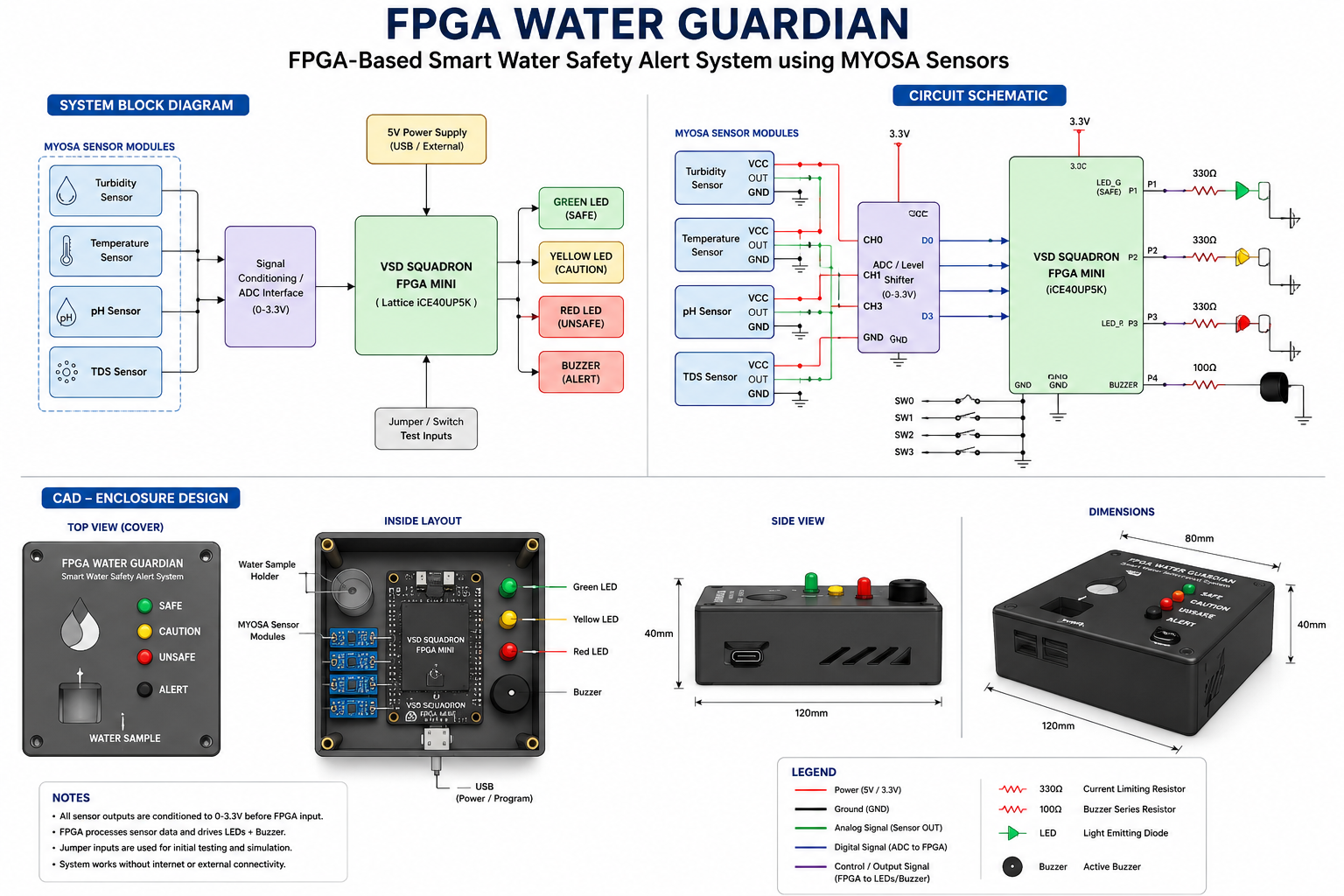
KAMALESH E
Published © GPL3+

Neuromorphic Water Guardian

A low-cost FPGA system that turns sensor readings into clear Safe, Caution, and Unsafe water alerts.

AdvancedFull instructions provided24 hours38
Neuromorphic Water Guardian

Things used in this project

Hardware components

VSD Squadron FPGA Mini board
×1
MYOSA sensor modules
×1

Software apps and online services

ubuntu linux
os used
FPGA compiler

Story

Read more

Schematics

main project setup

File missing, please reupload.

main project setup

main document

Code

main.v

Verilog
// ================================================================
// Project: FPGA-Based Smart Water Safety Alert System
// Board  : VSDSquadron FPGA Mini / iCE40UP5K
// Author : Kamalesh E
//
// Description:
// This project receives four digital water-quality warning inputs:
// 1. ph_bad
// 2. turbidity_bad
// 3. tds_bad
// 4. temp_bad
//
// It computes a risk level using FPGA logic and drives:
// Green LED  -> Safe
// Yellow LED -> Caution
// Red LED    -> Unsafe
// Buzzer     -> Danger alarm
//
// The risk decision uses a bio-inspired accumulator.
// If abnormal inputs continue, risk slowly increases.
// If inputs become normal, risk slowly decreases.
// ================================================================

module top (
    input  wire ph_bad,
    input  wire turbidity_bad,
    input  wire tds_bad,
    input  wire temp_bad,

    output reg  green_led,
    output reg  yellow_led,
    output reg  red_led,
    output reg  buzzer
);

    // ------------------------------------------------------------
    // Internal high-frequency oscillator
    // iCE40UP5K supports internal HF oscillator through SB_HFOSC.
    // We use it so no external clock pin is required.
    // ------------------------------------------------------------

    wire clk;

    SB_HFOSC #(
        .CLKHF_DIV("0b10")   // Divided clock, typically around 12 MHz
    ) internal_oscillator (
        .CLKHFPU(1'b1),
        .CLKHFEN(1'b1),
        .CLKHF(clk)
    );

    // ------------------------------------------------------------
    // Slow tick generator
    // This creates a slower timing pulse for risk update and buzzer.
    // ------------------------------------------------------------

    reg [23:0] slow_counter = 24'd0;
    reg slow_tick = 1'b0;

    always @(posedge clk) begin
        slow_counter <= slow_counter + 1'b1;

        if (slow_counter == 24'd6_000_000) begin
            slow_counter <= 24'd0;
            slow_tick <= 1'b1;
        end else begin
            slow_tick <= 1'b0;
        end
    end

    // ------------------------------------------------------------
    // Count how many sensor conditions are bad
    // bad_count range:
    // 0 -> all normal
    // 1 -> one abnormal parameter
    // 2 -> two abnormal parameters
    // 3 -> three abnormal parameters
    // 4 -> all four abnormal
    // ------------------------------------------------------------

    wire [2:0] bad_count;

    assign bad_count = ph_bad + turbidity_bad + tds_bad + temp_bad;

    // ------------------------------------------------------------
    // Bio-inspired risk accumulator
    //
    // This behaves like a simple neuron membrane potential.
    // More abnormal inputs increase risk faster.
    // Normal condition slowly leaks/decreases risk.
    //
    // risk_accumulator range: 0 to 15
    // ------------------------------------------------------------

    reg [3:0] risk_accumulator = 4'd0;

    always @(posedge clk) begin
        if (slow_tick) begin

            // Case 1: No abnormal sensor
            // Risk slowly decreases
            if (bad_count == 3'd0) begin
                if (risk_accumulator > 4'd0)
                    risk_accumulator <= risk_accumulator - 1'b1;
                else
                    risk_accumulator <= 4'd0;
            end

            // Case 2: One abnormal sensor
            // Risk slowly increases
            else if (bad_count == 3'd1) begin
                if (risk_accumulator < 4'd15)
                    risk_accumulator <= risk_accumulator + 1'b1;
                else
                    risk_accumulator <= 4'd15;
            end

            // Case 3: Two abnormal sensors
            // Risk increases faster
            else if (bad_count == 3'd2) begin
                if (risk_accumulator < 4'd14)
                    risk_accumulator <= risk_accumulator + 2'd2;
                else
                    risk_accumulator <= 4'd15;
            end

            // Case 4: Three or four abnormal sensors
            // Risk increases very fast
            else begin
                if (risk_accumulator < 4'd12)
                    risk_accumulator <= risk_accumulator + 3'd3;
                else
                    risk_accumulator <= 4'd15;
            end
        end
    end

    // ------------------------------------------------------------
    // Alert decision logic
    //
    // risk_accumulator 0 to 3   -> Safe
    // risk_accumulator 4 to 8   -> Caution
    // risk_accumulator 9 to 15  -> Danger
    // ------------------------------------------------------------

    reg [1:0] state;

    localparam SAFE    = 2'b00;
    localparam CAUTION = 2'b01;
    localparam DANGER  = 2'b10;

    always @(*) begin
        if (risk_accumulator <= 4'd3)
            state = SAFE;
        else if (risk_accumulator <= 4'd8)
            state = CAUTION;
        else
            state = DANGER;
    end

    // ------------------------------------------------------------
    // Buzzer pattern generator
    //
    // SAFE    -> buzzer off
    // CAUTION -> slow beep
    // DANGER  -> fast beep
    // ------------------------------------------------------------

    reg [22:0] beep_counter = 23'd0;

    always @(posedge clk) begin
        beep_counter <= beep_counter + 1'b1;
    end

    wire slow_beep;
    wire fast_beep;

    assign slow_beep = beep_counter[22];
    assign fast_beep = beep_counter[20];

    // ------------------------------------------------------------
    // Output control
    // ------------------------------------------------------------

    always @(*) begin
        // Default all outputs OFF
        green_led  = 1'b0;
        yellow_led = 1'b0;
        red_led    = 1'b0;
        buzzer     = 1'b0;

        case (state)

            SAFE: begin
                green_led  = 1'b1;
                yellow_led = 1'b0;
                red_led    = 1'b0;
                buzzer     = 1'b0;
            end

            CAUTION: begin
                green_led  = 1'b0;
                yellow_led = 1'b1;
                red_led    = 1'b0;
                buzzer     = slow_beep;
            end

            DANGER: begin
                green_led  = 1'b0;
                yellow_led = 1'b0;
                red_led    = 1'b1;
                buzzer     = fast_beep;
            end

            default: begin
                green_led  = 1'b0;
                yellow_led = 1'b0;
                red_led    = 1'b0;
                buzzer     = 1'b0;
            end

        endcase
    end

endmodule

pcf file

C/C++
# ================================================================
# PCF file for VSDSquadron FPGA Mini / iCE40UP5K
# Verify these FPGA package pins with your board datasheet/pinout.
# Change pin numbers if your board header mapping is different.
# ================================================================

# Input pins
set_io ph_bad          9
set_io turbidity_bad   10
set_io tds_bad         11
set_io temp_bad        12

# Output pins
set_io green_led       13
set_io yellow_led      18
set_io red_led         19
set_io buzzer          20

Credits

KAMALESH E
1 project • 1 follower
Third-year Electronics and Communication Engineering student at Government College of Technology-Coimbatore

Comments