


Hardware components | ||||||
| × | 1 | ||||
Software apps and online services | ||||||
| ||||||
Because digital filters can be computationally demanding and quite often are used for real-time signals, FPGA are a natural choice for digital filters in demanding conditions.
In this project I'm using the MYIR development board MYD-CZU3EG to develop and test different filter architectures on FPGA. The filters are written in Verilog as well as a chirp generator source file. The filter performance is captured by using Vivado ILA (Integrated Logic Analyzer) and JTAG together with Vivado Hardware Manager.
FIR filters are a very common tool in DSP (Digital Signal Processing). The other type of digital filters are IIR. The FIR type is more commonly used due to being intrinsically stable (IIR may not be...).
FIR filters can be lowpass, highpass, bandpass or band-reject (also called notch filter). A FIR filter involves a number of coefficients (N) and the last N signal samples.
Filter design stageThe basic parameters of a filter are the cut frequency and the slope (how sharp it is). There are plenty of calculators online that will give you the parameters for a FIR filter. If you have access to Matlab, that will be all you need. If not, you can use GNU Octave, it's open source, free, runs on Windows and Linux and it's even compatible with Matlab.
When you open octave you need to load the signal package for filters:
pkg load signalThe function used to calculate the filter coefficients is fir1:
B = fir1 (N, W, TYPE, WINDOW, NOSCALE)Where:
- N is the order of the filter (returns N+1 coefficients)
- W is the cut frequency (or a vector of two for bandpass, bandreject type). Note that W is a fraction of Fs (the sampling frequency), not an absolute frequency.
- TYPE is "low", "high", "stop", "pass", the filyer type. Default is lowpass.
- WINDOW is a string indicating the windowing applied. Default is Hamming.
- If NOSCALE is "noscale", the coefficients will not be normalized. The default is to normalize coefficients to have a gain 1 in the passband.
To generate the coefficients for a lowpass filter with order 20 and cut frequency 0.2 Fs, simply type:
b = fir1(20, 0.2);The response can be plotted with:
freqz(b)If you want to see the response in the time domain, a chirp function (a signal that increases its frequency) can be used. I generate one with these lines:
k = 0:999;
df = pi/1000;
s = cos(k .*k *df/2);
And plot it with:
plot(s)To apply the filter before (with coefficients in vector b) to this chirp signal (in variable s), you can do:
y = filter2(b, s);Or just plot the result straight away:
plot(filter2(b,s)The FIR filter developed above with Octave uses floating point coefficients and maths. Digital filters in FPGA can also use floats but quite often one can get a very similar result with an integer representation, using notably less resources.
It is common and handy to use a fixed-point representation, where the lower (rightmost) bits represent fractions of unity in binary (1/2, 1/4, 1/8, etc, in a similar way fractional digits represent 1/10, 1/100, 1/1000, etc)
Fixed-point formats are sometimes expressed as qM.N where M and N are the number of bits for the integer and fractional part. The example above is q10.6.
Fixed-point arithmetics can be a bit tricky because there is no warning about overflow and funny things happen... however, it is very useful.
Arithmetics with fixed-point values is like with normal integers, but one has to keep in mind:
1. Addition and subtraction needs at least the same number of fractional bits.For example, to add a q10.6 to a q12.4, one of them must be converted (shifted) to the other's format.
2. Product and quotient will add or subtract the number of fractional bits. For example, a q8.8 multiplied by a q10.6 will produce a q18.24. The same numbers divided will produce a format with 2 fractional bit (8-6)
3. Addition need one more bit for the result. Adding, for example two q10.6 needs a q11.6 for the result. The same applies to subtraction when using signed types (because subtracting from a negative number will make it bigger in absolute value).
4. Product with signed types can use one bit less for the result (because two sign bits merge into one). For example, multiplying two signed q10.6 can be stored in a signed q19.12.
5. Signed and unsigned types cannot be mixed. For example an unsigned q8.8 integer part can represent from 0 to 255 but if signed it will represent from -128 to +127 and operations will fail.
A chirp generator in VerilogThe file chirp.v implements the chirp generator that will be the source for the filters. It can be dropped into a block diagram and connected to an ILA to capture the output. I use the PS as a clock generator, there is no software running on it.
After building, programming the FPGA, connecting to ILA and triggering, it looks like that:
Going back to the previous design in Octave, we have these floating point coefficients:
An easy way to convert them to fixed-point is by multiplying by a power of 2 and rounding to integers, here I choose 20 fractional bits:
With these coefficients, the filter is implemented in the fir.v file, where each instantiated stage is in the fir_stage.v file.
The filter can be added to the block diagram and connected to the chirp source and ILA (one additional input).
And again connect to ILA, add the additional signal and trigger:
Text books present digital filters in different 'forms' or ways to implement them. It's the same filter, just the operations arranged in a different way. The direct (or canonical) form is straight from the mathematical equation:
However, this implementation is not very practical because it implies that all summations are done at once. The transpose form just brings the delay elements to after the summations:
The point here is that math operations (products and sums) in a procedural block already imply a delay. My implementation follows the transpose form.
Finally the cascade form splits de coefficients in groups of order 1 and 2:
Most FIR filters have either symmetric or antisymmetric coefficients. The previous low pass example is symmetric. Antisymmetric would be with values mirrored and with opposite sign.
This can be exploited to halve the number of products, by adding the inputs that are to be multiplied by the same coefficient. Because multipliers are more complex than adders, there is an overall reduction in resources.
Below is an example of the symmetric implementation in direct form. Note how the first and last x value are added before multiplication by h[0], the 2nd and last-but-one also added before h[1], etc.
There is also a transpose symmetric form.
Higher order filtersIt isn't uncommon for FIR filters to have hundreds of coefficients. To show the performance and the savings due to symmetry, I created an order 200 filter with:
b200=fir1(200, 0.2);Below is the resource usage for the non-symmetric and symmetric implementations. Note that most of the BRAM usage is due to the ILA. I expected about half of the usage but is not the case... I will look into that later on, it could be that it is using a whole DSP48 cell for the extra adder so what it saves on one hand is used on the other.
The filter performs as expected. Two things to note are:
1. The sharper cutoff, compared with the previous one.
2. The increased delay, always proportional to the filter order.
This is a quick and hopefully easy to follow tutorial on how to design, test and deploy FIR filters on FPGA using Verilog RTL. Filter design is a much wider field and I tried to cover the most common cases as an introduction.
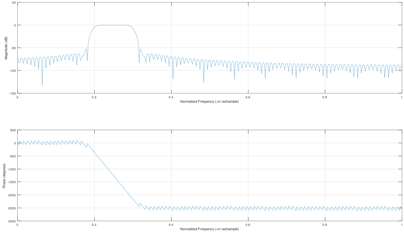
From the files included, one should be able to create similar filters for different specifications. For example, if we were need a passband filter, order 200, with cut frequencies 0.2 Fs and 0.3 Fs, we do this in Octave:
And convert the coefficients to q0.20 with:
Then duplicate one of the verilog files and replace the coefficients there. I have done this in fir_pb_200.v. Then just build the bitstream and run it with the chirp source, here is the result:


Comments