

Hardware components | ||||||
 |
| × | 1 | |||
| × | 1 | ||||
| × | 1 | ||||
Software apps and online services | ||||||
 |
| |||||
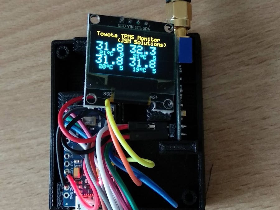
This is an enhancement from a similar project of mine for Toyota TPMS found here on Hackster.io. Please see that project for the full explanation, the hardware and circuit diagrams (which are unchanged for this project). The only change is in the software which is documented here.
This was done in collaboration with Banni (thank you) as I did not have a Renault TPMS tyre at the time.
Once again, thanks go to the RTL_433 team for their invaluable work on the protocol decoding for SDR.
Here is an example of a Renault TPMS transmission:
#include <EEPROM.h>
#include <Wire.h>
#include <SPI.h>


#include "globals.h"
#include "CC1101.h"
#include "Display.h"
//#include "ToyotaRead.h"
#include "RenaultRead.h"


void SendDebug(String Mess)
{
  Serial.println(Mess);
}


void setup() {

  byte resp;
  unsigned int t;
  int LEDState = LOW;
  int i;
  int mcount;

  //SPI CC1101 chip select set up
  pinMode(CC1101_CS, OUTPUT);
  digitalWrite(CC1101_CS, HIGH);


  Serial.begin(115200);


  pinMode(LED_RX, OUTPUT);
  pinMode(RXPin, INPUT);


  SPI.begin();
  //initialise the CC1101
  CC1101_reset();

  delay(2000);

  Serial.println("Starting...");


  setIdleState();
  digitalWrite(LED_RX, LED_OFF);

  resp = readStatusReg(CC1101_PARTNUM);
  Serial.print(F("Part no: "));
  Serial.println(resp, HEX);

  resp = readStatusReg(CC1101_VERSION);
  Serial.print(F("Version: "));
  Serial.println(resp, HEX);


#if USE_ADAFRUIT
  if (!display.begin(SSD1306_EXTERNALVCC, I2C_ADDRESS)) {
    Serial.println(F("SSD1306 allocation failed"));
    for (;;); // Don't proceed, loop forever
  }
#else
  Wire.begin();
  Wire.setClock(400000L);
  display.begin(&Adafruit128x64, I2C_ADDRESS);
  display.setFont(Adafruit5x7);

#endif


  Serial.println(F("SSD1306 initialised OK"));


  digitalWrite(LED_RX, LED_ON);
  LEDState = HIGH;

  pinMode(DEBUGPIN, OUTPUT);

#ifndef USE_PROGMEMCRC
  CalulateTable_CRC8();
#endif

  // Clear the buffer
#if USE_ADAFRUIT
  display.clearDisplay();
  display.display();
#else
  display.clear();
#endif

  InitTPMS();


  digitalWrite(LED_RX, LED_OFF);

  setRxState();
}

void loop() {
  // put your main code here, to run repeatedly:
  int i;
  static long lastts = millis();
  float diff;
  int RXBitCount = 0;
  int ByteCount = 0;
  byte crcResult;
  boolean TPMS_Changed;


  TPMS_Changed = Check_TPMS_Timeouts();

  InitDataBuffer();

  //wait for carrier status to go low
  while (GetCarrierStatus == true)
  {
  }

  //wait for carrier status to go high  looking for rising edge
  while (GetCarrierStatus == false)
  {
  }

  if (GetCarrierStatus() == true)
  { //looks like some data coming in...

    ByteCount = ReceiveMessage();
    //Serial.println(ByteCount);
    if (ByteCount == 9)
    {


      crcResult = Compute_CRC8(ByteCount);


      if (crcResult != 0)
      {
//        Serial.print(F("CRC: "));
//        Serial.println(crcResult, HEX);
//        Serial.println(F("CRC Check failed"));
        //PrintData(BitCount);
      }
      else
      {
        //decode the message...
        DecodeTPMS();
        TPMS_Changed = true;  //indicates the display needs to be updated.
      }
    }

    if (TPMS_Changed == true)
    {
      UpdateDisplay();
      TPMS_Changed = false;
   }
  }


}
//#define USE_ADAFRUIT 1
#define USE_TEXTONLY 1

#if USE_ADAFRUIT
   #include <Adafruit_GFX.h>
   #include <Adafruit_SSD1306.h>


   #define SCREEN_WIDTH 128 // OLED display width, in pixels
   #define SCREEN_HEIGHT 64 // OLED display height, in pixels
   Adafruit_SSD1306 display(SCREEN_WIDTH, SCREEN_HEIGHT,  &Wire, -1);


  void ShowTitle()
  {
    display.clearDisplay();
    display.setFont(Adafruit5x7);
    display.setTextSize(1);             // Normal 1:1 pixel scale
    display.setTextColor(WHITE, BLACK);       // Draw white text

    display.setCursor(0, 0);
    display.println("Renault TPMS Monitor");
    display.println("   (JSM Solutions)");


  }

  void UpdateDisplay()
  {
    int i;
    int x = 0;
    int y = 0;
    char s[6];

    ShowTitle();

    display.setFont(Adafruit5x7);
    display.setTextSize(2);

    for (i = 0; i < 4; i++)
    {
      switch (i)
      {
        case 0:
          x = 0;
          y = 16;
          break;
        case 1:
          x = 64;
          y = 16;
          break;
        case 2:
          x = 0;
          y = 48;
          break;
        case 3:
          x = 64;
          y = 48;
          break;
      }


      display.setCursor(x, y);

      if (TPMS[i].TPMS_ID != 0)
      {

        // in kpa
        //int kpa;
        //kpa = (int) (TPMS[i].TPMS_Pressure + 0.5);
        //sprintf(s,"%3d", kpa);

        //in bar...
        dtostrf(TPMS[i].TPMS_Pressure/100.0, 3, 2, s);

        //in psi
        //dtostrf(TPMS[i].TPMS_Pressure/6.895, 3, 1, s);

        display.print(s);
      }
    }
    display.display();

  }

#else
   #include "SSD1306Ascii.h"
   #include "SSD1306AsciiWire.h"

   SSD1306AsciiWire display;


   void ShowTitle()
  {
    display.clear();

    display.set1X();             // Normal 1:1 pixel scale
    //display.setTextColor(WHITE, BLACK);       // Draw white text

    display.setCursor(0, 0);
    display.println("Renault TPMS Monitor");
    display.println("      (JSM Solutions)");


  }

  char DisplayTimeoutBar(unsigned long TimeSinceLastUpdate)
  {
      int HowCloseToTimeout;
      HowCloseToTimeout = (int)(TimeSinceLastUpdate/(TPMS_TIMEOUT/5));

      switch(HowCloseToTimeout)
      {
        case 0:
           //return(FONTBAR_7);
           return('5');
           break;
        case 1:
           //return(FONTBAR_5);
           return('4');
           break;
        case 2:
           //return(FONTBAR_3);
           return('3');
           break;
        case 3:
           //return(FONTBAR_2);
           return('2');
           break;
        case 4:
           //return(FONTBAR_1);
           return('1');
           break;
        default:
           //return(FONTBAR_0);
           return('0');
           break;

      }
  }

  void UpdateDisplay()
  {
    int i;
    int x = 0;
    int y = 0;
    char s[6];

    ShowTitle();


    for (i = 0; i < 4; i++)
    {
      switch (i)
      {
        case 0:
          x = 0;
          y = 2;
          break;
        case 1:
          x = 59;
          y = 2;
          break;
        case 2:
          x = 0;
          y = 5;
          break;
        case 3:
          x = 59;
          y = 5;
          break;
      }


      display.setCursor(x, y);

      if (TPMS[i].TPMS_ID != 0)
      {
        display.setFont(Adafruit5x7);
        display.set2X();

        // in kpa
        //int kpa;
        //kpa = (int) (TPMS[i].TPMS_Pressure + 0.5);
        //sprintf(s,"%3d", kpa);

        //in bar...
        dtostrf(TPMS[i].TPMS_Pressure/100.0, 3, 2, s);

        //in psi
        //dtostrf(TPMS[i].TPMS_Pressure/6.895, 3, 1, s);
        display.print(s);

        display.setCursor(x, y+2);
        display.setFont(Adafruit5x7);
        display.set1X();
        dtostrf(TPMS[i].TPMS_Temperature, 2, 0, s);
        display.print(" ");
        display.print(s);
        display.setFont(System5x7);
        display.print(char(128));  //degrees symbol
        display.setFont(Adafruit5x7);
        display.print("C");
        display.print("  ");

        //display vertical bar showing how long since last update 7 bars = recent 1 bar = nearing timeout (at timeout it will be removed from display altogether)
        display.setFont(System5x7);
        display.print(DisplayTimeoutBar(millis() - TPMS[i].lastupdated));
      }


    }


  }
#endif
void ClearTPMSData(int i)
{
  if (i > 4)
    return;

  TPMS[i].TPMS_ID = 0;
  TPMS[i].lastupdated = 0;

}

void PulseDebugPin(int width_us)
{
  digitalWrite(DEBUGPIN, HIGH);
  delayMicroseconds(width_us);
  digitalWrite(DEBUGPIN, LOW);
}


int GetPreferredIndex(unsigned long ID)
{
  int i;

  for (i = 0; i  < (sizeof(IDLookup) / sizeof(IDLookup[0])); i++)
  {
    if (IDLookup[i] == ID)
    {
      return (i);
    }

  }
  return (-1);
}

void PrintBits(byte StartPoint, byte Count)
{
  byte i;
  for (i = 0; i < Count; i++)
  {
    Serial.print(IncomingBits[StartPoint + i]);
    Serial.print(F(","));
  }
  Serial.println(F(""));
}
void PrintTimings(byte StartPoint, byte Count)
{
  byte i;
  for (i = 0; i < Count; i++)
  {
    Serial.print(Timings[StartPoint + i]);
    Serial.print(F(","));
  }
  Serial.println(F(""));
  //    for (i = 0;i<Count;i++)
  //    {
  //          Serial.print(BitTimings[StartPoint + i]);
  //          Serial.print(",");
  //    }
  //    Serial.println("");


}

void PrintData(byte Count)
{
  byte i;
  byte hexdata;
  for (i = 0; i < Count; i++)
  {
    Serial.print(IncomingBits[i]);
    hexdata = (hexdata << 1) + IncomingBits[i];
    if ((i + 1) % 8 == 0)
    {
      Serial.print(F(" ["));
      Serial.print(hexdata, HEX);
      Serial.print(F("] "));
      hexdata = 0;
    }
  }
  Serial.println(F(""));
}


void InitTPMS()
{
  int i;

  for (i = 0; i < 4; i++)
  {
    ClearTPMSData(i);
  }

  UpdateDisplay();

}

void UpdateTPMSData(int index, unsigned long ID, unsigned int status, float Temperature, float Pressure)
{

  if (index >= 4)
    return;

  TPMS[index].TPMS_ID = ID;
  TPMS[index].TPMS_Status = status;
  TPMS[index].lastupdated = millis();
  TPMS[index].TPMS_Temperature = Temperature;
  TPMS[index].TPMS_Pressure = Pressure;
}

void DisplayStatusInfo()
{
  Serial.print (F("FreqOffset: "));
  Serial.print (FreqOffset);
  Serial.print (F("  DemodLinkQuality: "));
  Serial.print (DemodLinkQuality);
  Serial.print (F("  RSSI: "));
  Serial.println (RSSIvalue);
}

boolean Check_TPMS_Timeouts()
{
   byte i;
   boolean ret = false;

    //clear any data not updated in the last 5 minutes
  for (i = 0; i < 4; i++)
  {
    #ifdef SHOWDEGUGINFO
      Serial.print(TPMS[i].TPMS_ID, HEX);
      Serial.print(F("   "));
    #endif

    if ((TPMS[i].TPMS_ID != 0) && (millis() - TPMS[i].lastupdated > TPMS_TIMEOUT))
    {
      #ifdef SHOWDEGUGINFO
         Serial.print(F("Clearing ID "));
         Serial.println(TPMS[i].TPMS_ID, HEX);
      #endif
      ClearTPMSData(i);
      ret = true;
    }

  }
  return(ret);
}

void DecodeTPMS()
{
  int i;
  unsigned long id = 0;
  unsigned int status, pressure1, pressure2, temp;
  float realpressure;
  float realtemp;
  bool IDFound = false;
  int prefindex;

  for (i = 5; i >= 3; i--)
  {
    id = id << 8;
    id = id + RXBytes[i];

  }

  // id = (unsigned)RXBytes[0] << 24 | RXBytes[1] << 16 | RXBytes[2] << 8 | RXBytes[3];

  status = RXBytes[0] >> 2;

  pressure1 = (RXBytes[0] & 0x03)  << 8 | RXBytes[1];

  temp = RXBytes[2];

  pressure2 = pressure1;


  if (pressure1 != pressure2)
  {
    Serial.println(F("Pressure check mis-match"));
    return;
  }

  realpressure = pressure1 * 0.75;
  realtemp = temp - 30.0;

#ifdef SHOWDEGUGINFO
  Serial.print(F("ID: "));
  Serial.print(id, HEX);
  Serial.print(F("   Status: "));
  Serial.print(status);
  Serial.print(F("   Temperature: "));
  Serial.print(realtemp);
  Serial.print(F("   Tyre Pressure: "));
  Serial.print(realpressure);
  Serial.println(F(""));
#endif

  //DisplayStatusInfo();

  //update the array of tyres data
  for (i = 0; i < 4; i++)
  { //find a matching ID if it already exists
    if (id == TPMS[i].TPMS_ID)
    {
      UpdateTPMSData(i, id, status, realtemp, realpressure);
      IDFound = true;
      break;
    }

  }

  //no matching IDs in the array, so see if there is an empty slot to add it into, otherwise, ignore it.
  if (IDFound == false)
  {

    prefindex = GetPreferredIndex(id);
    if (prefindex == -1)
    { //not found a specified index, so use the next available one..
      for (i = 0; i < 4; i++)
      {
        if (TPMS[i].TPMS_ID == 0)
        {
          UpdateTPMSData(i, id, status, realtemp, realpressure);
        }
      }
    }
    else
    { //found a match in the known ID list...
      UpdateTPMSData(prefindex, id, status, realtemp, realpressure);
    }

  }


  #ifdef SHOWDEGUGINFO
     Serial.println(F(""));
  #endif


  //UpdateDisplay();
}


#ifndef USE_PROGMEMCRC
  void CalulateTable_CRC8()
  {
    const byte generator = 0x07;

    /* iterate over all byte values 0 - 255 */
    for (int divident = 0; divident < 256; divident++)
    {
      byte currByte = (byte)divident;
      /* calculate the CRC-8 value for current byte */
      for (byte bit = 0; bit < 8; bit++)
      {
        if ((currByte & 0x80) != 0)
        {
          currByte <<= 1;
          currByte ^= generator;
        }
        else
        {
          currByte <<= 1;
        }
      }
      /* store CRC value in lookup table */
      crctable[divident] = currByte;
      Serial.print("0x");
      if (currByte < 16)
         Serial.print("0");
      Serial.print(currByte,HEX);
      Serial.print(", ");
    }
  }
#endif

byte Compute_CRC8( int bcount)
{
  byte crc = 0x00;
  int c;
  for (c = 0; c < bcount; c++)
  {
    byte b = RXBytes[c];
    /* XOR-in next input byte */
    byte data = (byte)(b ^ crc);
    /* get current CRC value = remainder */
    #ifdef USE_PROGMEMCRC
        crc = (byte)(pgm_read_byte(&crctable2[data]));
    #else
        crc = (byte)(crctable[data]);
    #endif

  }

  return crc;
}


void ClearRXBuffer()
{
  int i;

  for (i = 0; i < sizeof(RXBytes); i++)
  {
    RXBytes[i] = 0;
  }
}

//********************************************  interrupt handler   *******************************
bool FirstEdgeState = LOW;
void EdgeInterrupt()
{
  unsigned long ts = micros();
  unsigned long BitWidth;


  if (TimingsIndex == 0)
  {
     //remember the state of the first entry (all other entries will assume to be toggled from this state)
     FirstEdgeState = digitalRead(RXPin);
  }


  if (TimingsIndex == 255)
  {//buffer full - don't accpet anymore
    return;
  }

  BitWidth = ts - LastEdgeTime_us;
  LastEdgeTime_us = ts;

  if (BitWidth <= 12)  //ignore glitches
  {
    return;
  }

  if (BitWidth > 255)
    BitWidth = 255;

  Timings[TimingsIndex++] = (byte)BitWidth;

}

//********************************************  end of interrupt handler   *******************************

bool IsTooShort(byte Width)
{
  if (Width < 35)
  {
    return (true);
  }
  else
  {
    return (false);
  }
}

bool IsTooLong(byte Width)
{
  if (Width > 120)
  {
    return (true);
  }
  else
  {
    return (false);
  }
}

bool IsValidSync(byte Width)
{
  if (Width >=  175)
  {
    return (true);
  }
  else
  {
    return (false);
  }
}

bool IsValidShort(byte Width)
{
  if ((Width >= 35) && (Width <= 68))
  {
    return (true);
  }
  else
  {
    return (false);
  }
}


bool IsValidLong(byte Width)
{
  if ((Width >= 80) && (Width <= 120))
  {
    return (true);
  }
  else
  {
    return (false);
  }
}

int ValidateBit()
{
  byte BitWidth = Timings[CheckIndex];
  byte BitWidthNext = Timings[CheckIndex + 1];

  if (IsValidLong(BitWidth))
  {
    return (1);
  }

  if (IsValidShort(BitWidth))
  {
    return (0);
  }

  if (IsValidSync(BitWidth))
  {
    return (2);
  }


  return (-1);

}

static inline uint8_t bit_at(const uint8_t *bytes, unsigned bit)

{
    return (uint8_t)(bytes[bit >> 3] >> (7 - (bit & 7)) & 1);
}

int FindManchesterStart()
{
  int i;


  //Renault TMS header pattern
   const uint8_t pattern[] = {0xAA, 0xA9};
   int pattern_bits_len = 16;
   unsigned int ipos = 0;
   unsigned int ppos = 0; // cursor on init pattern

    while ((ipos < BitCount-3) && (ppos < pattern_bits_len))
    {
        if (IncomingBits[ipos] == bit_at(pattern, ppos))
        {
            ppos++;
            ipos++;
            if (ppos == pattern_bits_len)
                return ipos;
        }
        else
        {
            ipos -= ppos;
            ipos++;
            ppos = 0;
        }
    }

    // Not found
    return -1;

}

void InvertBitBuffer()
{
   int i;

   for (i = 0;i < BitCount;i++)
   {
      IncomingBits[i] = !IncomingBits[i];
   }

}

void ConvertTimingsToBits()
{
   int i;

   bool CurrentState = FirstEdgeState;

   BitCount = 0;


   for (i=0;i<= TimingsIndex;i++)
   {
      if (IsValidShort(Timings[i]) )
      {
         IncomingBits[BitCount++] = CurrentState;
      }
      if (IsValidLong(Timings[i]) )
      {
         IncomingBits[BitCount++] = CurrentState;
         IncomingBits[BitCount++] = CurrentState;
      }
      if (IsTooShort(Timings[i] ) || IsTooLong(Timings[i] ) )
      {
         if (BitCount == 0)
         { //invalid bit timing, ignore if at start of data stream

         }
         else
         {// end the conversion
            return;
         }
      }

      CurrentState = !CurrentState;

      if (BitCount >= MAXBITS-1)
      {
         return;
      }
   }

}

int ManchesterDecode(int StartIndex)
{
   int i;
   bool bit1, bit2;
   byte b = 0;
   byte n = 0;

   RXByteCount = 0;
   for (i = StartIndex; i< BitCount-1;i+=2)
   {
      bit1 = IncomingBits[i];
      bit2 = IncomingBits[i+1];

      if (bit1 == bit2)
         return RXByteCount;

    b = b << 1;
    b = b + (bit2 == true? 1:0);
    n++;
    if (n == 8)
    {
      RXBytes[RXByteCount] = b;
      RXByteCount++;
      n = 0;
      b = 0;
    }

   }

   return RXByteCount;

}


int ValidateTimings()
{


  byte BitWidth;
  byte BitWidthNext;
  byte BitWidthNextPlus1;
  byte BitWidthPrevious;
  byte diff = TimingsIndex - CheckIndex;
  //unsigned long tmp;
  bool WaitingTrailingZeroEdge = false;
  int ret;
  int ManchesterStartPos = -1;
  byte bcount = 0;

  StartDataIndex = 0;

  if (TimingsIndex < 16 + 72)  //header + valid data (minimum)
  { //not enough in the buffer to consider a valid message
    Serial.println(F("Insufficient data in buffer"));
    return -1;
  }

  if (TimingsIndex > 200)  //header + valid data (minimum)
  { //not enough in the buffer to consider a valid message
    Serial.println(F("Excessive data in buffer"));
    return -1;
  }

  //Serial.print("Timings index = ");
  //Serial.println(TimingsIndex);

  ConvertTimingsToBits();

  //InvertBitBuffer();


  ManchesterStartPos = FindManchesterStart();
  Serial.println(ManchesterStartPos);
  if (ManchesterStartPos == -1 )
  {
    Serial.println("Renault header not found");

    return -1;
  }
  else
  {
     #ifdef SHOWDEGUGINFO
       Serial.print("Timings index = ");
       Serial.println(TimingsIndex);
       Serial.print("CD Width = ");
       Serial.println(CD_Width);
       Serial.print("Bit count = ");
       Serial.println(BitCount);
       PrintTimings(0,TimingsIndex);
       PrintBits(0,BitCount);
    #endif
  }

  bcount = ManchesterDecode(ManchesterStartPos);
  if (bcount == 9)
  {
     return 9;
  }
  else
  {
    return -1;
  }


}


void InitDataBuffer()
{
  BitIndex = 0;
  BitCount = 0;
  ValidBlock = false;
  //WaitingTrailingZeroEdge = false;
  WaitingFirstEdge  = true;
  CheckIndex = 0;
  TimingsIndex = 0;
  SyncFound = false;
  //digitalWrite(DEBUGPIN, LOW);

}

void UpdateStatusInfo()
{
  FreqOffset = readStatusReg(CC1101_FREQEST);
  DemodLinkQuality = readStatusReg(CC1101_LQI);
  RSSIvalue = readStatusReg(CC1101_RSSI);
}

int ReceiveMessage()
{

  //Check bytes in FIFO
  int FIFOcount;
  int resp;
  int ValidRenault = -1;

  //set up timing of edges using interrupts...
  LastEdgeTime_us = micros();
  CD_Width = micros();

  attachInterrupt(digitalPinToInterrupt(RXPin), EdgeInterrupt, CHANGE);
  while (GetCarrierStatus() == true)
  {
  }
  detachInterrupt(digitalPinToInterrupt(RXPin));

  //digitalWrite(DEBUGPIN,LOW);

  CD_Width = micros() - CD_Width;
  if ((CD_Width >= 9500) && (CD_Width <= 9900))
  {


    //Serial.println(F("Checking"));
    digitalWrite(LED_RX,LED_ON);
    CheckIndex = 0;
    ValidRenault = ValidateTimings();
    //Serial.println(F("Checking complete"));
    digitalWrite(LED_RX,LED_OFF);

    #ifdef SHOWDEGUGINFO
       Serial.print("Timings index = ");
       Serial.println(TimingsIndex);
       Serial.print("CD Width = ");
       Serial.println(CD_Width);
       PrintTimings(0,TimingsIndex);
    #endif
    return ValidRenault;
  }
  else
  {
    return(-1);
  }


}
enum RFSTATE
{
  RFSTATE_IDLE = 0,
  RFSTATE_RX,
  RFSTATE_TX
};


SPIClass spi;

/**
 * Frequency channels
 */
#define NUMBER_OF_FCHANNELS      10

/**
 * Type of transfers
 */
#define WRITE_BURST              0x40
#define READ_SINGLE              0x80
#define READ_BURST               0xC0

/**
 * Type of register
 */
#define CC1101_CONFIG_REGISTER   READ_SINGLE
#define CC1101_STATUS_REGISTER   READ_BURST


/**
 * Buffer and data lengths
 */
#define CCPACKET_BUFFER_LEN        64
#define CCPACKET_DATA_LEN          CCPACKET_BUFFER_LEN - 3

/**
 * Class: CCPACKET
 *
 * Description:
 * CC1101 data packet class
 */
struct CCPACKET
{
  public:
     //Data length
    unsigned char length;
     // Data buffer
    unsigned char data[CCPACKET_DATA_LEN];
     //* CRC OK flag
    bool crc_ok;
     // Received Strength Signal Indication
    unsigned char rssi;
     // Link Quality Index
    unsigned char lqi;
};


/**
 * Macros
 */

#define wait_Miso()  delay(3)
//while(digitalRead(PORT_SPI_MISO))
// Get GDO0 pin state
#define getGDO0state()  digitalRead(PORT_GDO0)
// Wait until GDO0 line goes high
#define wait_GDO0_high()  while(!getGDO0state()) {delay(1);}
// Wait until GDO0 line goes low
#define wait_GDO0_low()  while(getGDO0state()) {delay(1);}


/**
 * PATABLE & FIFO's
 */
#define CC1101_PATABLE           0x3E        // PATABLE address
#define CC1101_TXFIFO            0x3F        // TX FIFO address
#define CC1101_RXFIFO            0x3F        // RX FIFO address

/**
 * Command strobes
 */
#define CC1101_SRES              0x30        // Reset CC1101 chip
#define CC1101_SFSTXON           0x31        // Enable and calibrate frequency synthesizer (if MCSM0.FS_AUTOCAL=1). If in RX (with CCA):
                                             // Go to a wait state where only the synthesizer is running (for quick RX / TX turnaround).
#define CC1101_SXOFF             0x32        // Turn off crystal oscillator
#define CC1101_SCAL              0x33        // Calibrate frequency synthesizer and turn it off. SCAL can be strobed from IDLE mode without
                                             // setting manual calibration mode (MCSM0.FS_AUTOCAL=0)
#define CC1101_SRX               0x34        // Enable RX. Perform calibration first if coming from IDLE and MCSM0.FS_AUTOCAL=1
#define CC1101_STX               0x35        // In IDLE state: Enable TX. Perform calibration first if MCSM0.FS_AUTOCAL=1.
                                             // If in RX state and CCA is enabled: Only go to TX if channel is clear
#define CC1101_SIDLE             0x36        // Exit RX / TX, turn off frequency synthesizer and exit Wake-On-Radio mode if applicable
#define CC1101_SWOR              0x38        // Start automatic RX polling sequence (Wake-on-Radio) as described in Section 19.5 if
                                             // WORCTRL.RC_PD=0
#define CC1101_SPWD              0x39        // Enter power down mode when CSn goes high
#define CC1101_SFRX              0x3A        // Flush the RX FIFO buffer. Only issue SFRX in IDLE or RXFIFO_OVERFLOW states
#define CC1101_SFTX              0x3B        // Flush the TX FIFO buffer. Only issue SFTX in IDLE or TXFIFO_UNDERFLOW states
#define CC1101_SWORRST           0x3C        // Reset real time clock to Event1 value
#define CC1101_SNOP              0x3D        // No operation. May be used to get access to the chip status byte

/**
 * CC1101 configuration registers
 */
#define CC1101_IOCFG2            0x00        // GDO2 Output Pin Configuration
#define CC1101_IOCFG1            0x01        // GDO1 Output Pin Configuration
#define CC1101_IOCFG0            0x02        // GDO0 Output Pin Configuration
#define CC1101_FIFOTHR           0x03        // RX FIFO and TX FIFO Thresholds
#define CC1101_SYNC1             0x04        // Sync Word, High Byte
#define CC1101_SYNC0             0x05        // Sync Word, Low Byte
#define CC1101_PKTLEN            0x06        // Packet Length
#define CC1101_PKTCTRL1          0x07        // Packet Automation Control
#define CC1101_PKTCTRL0          0x08        // Packet Automation Control
#define CC1101_ADDR              0x09        // Device Address
#define CC1101_CHANNR            0x0A        // Channel Number
#define CC1101_FSCTRL1           0x0B        // Frequency Synthesizer Control
#define CC1101_FSCTRL0           0x0C        // Frequency Synthesizer Control
#define CC1101_FREQ2             0x0D        // Frequency Control Word, High Byte
#define CC1101_FREQ1             0x0E        // Frequency Control Word, Middle Byte
#define CC1101_FREQ0             0x0F        // Frequency Control Word, Low Byte
#define CC1101_MDMCFG4           0x10        // Modem Configuration
#define CC1101_MDMCFG3           0x11        // Modem Configuration
#define CC1101_MDMCFG2           0x12        // Modem Configuration
#define CC1101_MDMCFG1           0x13        // Modem Configuration
#define CC1101_MDMCFG0           0x14        // Modem Configuration
#define CC1101_DEVIATN           0x15        // Modem Deviation Setting
#define CC1101_MCSM2             0x16        // Main Radio Control State Machine Configuration
#define CC1101_MCSM1             0x17        // Main Radio Control State Machine Configuration
#define CC1101_MCSM0             0x18        // Main Radio Control State Machine Configuration
#define CC1101_FOCCFG            0x19        // Frequency Offset Compensation Configuration
#define CC1101_BSCFG             0x1A        // Bit Synchronization Configuration
#define CC1101_AGCCTRL2          0x1B        // AGC Control
#define CC1101_AGCCTRL1          0x1C        // AGC Control
#define CC1101_AGCCTRL0          0x1D        // AGC Control
#define CC1101_WOREVT1           0x1E        // High Byte Event0 Timeout
#define CC1101_WOREVT0           0x1F        // Low Byte Event0 Timeout
#define CC1101_WORCTRL           0x20        // Wake On Radio Control
#define CC1101_FREND1            0x21        // Front End RX Configuration
#define CC1101_FREND0            0x22        // Front End TX Configuration
#define CC1101_FSCAL3            0x23        // Frequency Synthesizer Calibration
#define CC1101_FSCAL2            0x24        // Frequency Synthesizer Calibration
#define CC1101_FSCAL1            0x25        // Frequency Synthesizer Calibration
#define CC1101_FSCAL0            0x26        // Frequency Synthesizer Calibration
#define CC1101_RCCTRL1           0x27        // RC Oscillator Configuration
#define CC1101_RCCTRL0           0x28        // RC Oscillator Configuration
#define CC1101_FSTEST            0x29        // Frequency Synthesizer Calibration Control
#define CC1101_PTEST             0x2A        // Production Test
#define CC1101_AGCTEST           0x2B        // AGC Test
#define CC1101_TEST2             0x2C        // Various Test Settings
#define CC1101_TEST1             0x2D        // Various Test Settings
#define CC1101_TEST0             0x2E        // Various Test Settings

/**
 * Status registers
 */
#define CC1101_PARTNUM           0x30        // Chip ID
#define CC1101_VERSION           0x31        // Chip ID
#define CC1101_FREQEST           0x32        // Frequency Offset Estimate from Demodulator
#define CC1101_LQI               0x33        // Demodulator Estimate for Link Quality
#define CC1101_RSSI              0x34        // Received Signal Strength Indication
#define CC1101_MARCSTATE         0x35        // Main Radio Control State Machine State
#define CC1101_WORTIME1          0x36        // High Byte of WOR Time
#define CC1101_WORTIME0          0x37        // Low Byte of WOR Time
#define CC1101_PKTSTATUS         0x38        // Current GDOx Status and Packet Status
#define CC1101_VCO_VC_DAC        0x39        // Current Setting from PLL Calibration Module
#define CC1101_TXBYTES           0x3A        // Underflow and Number of Bytes
#define CC1101_RXBYTES           0x3B        // Overflow and Number of Bytes
#define CC1101_RCCTRL1_STATUS    0x3C        // Last RC Oscillator Calibration Result
#define CC1101_RCCTRL0_STATUS    0x3D        // Last RC Oscillator Calibration Result


#define CC1101_DEFVAL_IOCFG2     0x0D        // GDO2 Output Pin Configuration - Serial out
#define CC1101_DEFVAL_IOCFG1     0x2E        // GDO1 Output Pin Configuration - not used
//#define CC1101_DEFVAL_IOCFG0     0x0D        // GDO0 Output Pin Configuration
#define CC1101_DEFVAL_IOCFG0     0x0E        // GDO0 Output Pin Configuration - Carrier Sense output
#define CC1101_DEFVAL_FIFOTHR    0x0F        // RX FIFO and TX FIFO Thresholds - 64 bytes in FIFO
#define CC1101_DEFVAL_SYNC1      0xD5        // Synchronization word, high byte  11010101 01001111
#define CC1101_DEFVAL_SYNC0      0x4F        // Synchronization word, low byte
#define CC1101_DEFVAL_PKTLEN     0x09        // Packet Length
#define CC1101_DEFVAL_PKTCTRL1   0x00        // Packet Automation Control
#define CC1101_DEFVAL_PKTCTRL0   0x30        // Packet Automation Control
#define CC1101_DEFVAL_ADDR       0x00        // Device Address
#define CC1101_DEFVAL_CHANNR     0x00        // Channel Number
#define CC1101_DEFVAL_FSCTRL1    0x0F        // Frequency Synthesizer Control (was 0x06)
#define CC1101_DEFVAL_FSCTRL0    0x00        // Frequency Synthesizer Control
// Carrier frequency = 868 MHz (not used)
#define CC1101_DEFVAL_FREQ2_868  0x21        // Frequency Control Word, High Byte
#define CC1101_DEFVAL_FREQ1_868  0x65        // Frequency Control Word, Middle Byte
#define CC1101_DEFVAL_FREQ0_868  0xCC        // Frequency Control Word, Low Byte
// Carrier frequency = 433.8798 MHz
#define CC1101_DEFVAL_FREQ2_433  0x10        // Frequency Control Word, High Byte
#define CC1101_DEFVAL_FREQ1_433  0xB0        // Frequency Control Word, Middle Byte
#define CC1101_DEFVAL_FREQ0_433  0x0C        // Frequency Control Word, Low Byte

#define CC1101_DEFVAL_MDMCFG4    0x59        // Modem Configuration (59 = data rate = 20kHz - actual data rate is 10kHz but due to bi-phase coding need to double the rate, RX bandwidth 325kHz)
#define CC1101_DEFVAL_MDMCFG3    0x93        // Modem Configuration (now 93 = data rate = 20kHz)
#define CC1101_DEFVAL_MDMCFG2    0x10        // Modem Configuration (GFSK, No Sync or Manchester coding)

#define CC1101_DEFVAL_MDMCFG1    0x22        // Modem Configuration Channel spacing 200kHz
#define CC1101_DEFVAL_MDMCFG0    0xF8        // Modem Configuration
#define CC1101_DEFVAL_DEVIATN    0x41        // Modem Deviation Setting (+/-28.56kHz)
#define CC1101_DEFVAL_MCSM2      0x07        // Main Radio Control State Machine Configuration
//#define CC1101_DEFVAL_MCSM1      0x30        // Main Radio Control State Machine Configuration
#define CC1101_DEFVAL_MCSM1      0x3C        // Main Radio Control State Machine Configuration
#define CC1101_DEFVAL_MCSM0      0x18        // Main Radio Control State Machine Configuration
#define CC1101_DEFVAL_FOCCFG     0x16        // Frequency Offset Compensation Configuration
#define CC1101_DEFVAL_BSCFG      0x6C        // Bit Synchronization Configuration
//#define CC1101_DEFVAL_AGCCTRL2   0x43        // AGC Control
#define CC1101_DEFVAL_AGCCTRL2   0xC6        // AGC Control
//#define CC1101_DEFVAL_AGCCTRL1   0x40        // AGC Control
#define CC1101_DEFVAL_AGCCTRL1   0x50        // AGC Control
#define CC1101_DEFVAL_AGCCTRL0   0x80        // AGC Control

#define CC1101_DEFVAL_WOREVT1    0x87        // High Byte Event0 Timeout
#define CC1101_DEFVAL_WOREVT0    0x6B        // Low Byte Event0 Timeout
#define CC1101_DEFVAL_WORCTRL    0xFB        // Wake On Radio Control
#define CC1101_DEFVAL_FREND1     0x56        // Front End RX Configuration
#define CC1101_DEFVAL_FREND0     0x10        // Front End TX Configuration

#define CC1101_DEFVAL_FSCAL3     0xE9        // Frequency Synthesizer Calibration
#define CC1101_DEFVAL_FSCAL2     0x2A        // Frequency Synthesizer Calibration
#define CC1101_DEFVAL_FSCAL1     0x00        // Frequency Synthesizer Calibration
#define CC1101_DEFVAL_FSCAL0     0x1F        // Frequency Synthesizer Calibration

#define CC1101_DEFVAL_RCCTRL1    0x41        // RC Oscillator Configuration
#define CC1101_DEFVAL_RCCTRL0    0x00        // RC Oscillator Configuration

#define CC1101_DEFVAL_FSTEST     0x59        // Frequency Synthesizer Calibration Control

#define CC1101_DEFVAL_PTEST      0x7F        // Production Test
#define CC1101_DEFVAL_AGCTEST    0x3F        // AGC Test

#define CC1101_DEFVAL_TEST2      0x81        // Various Test Settings
#define CC1101_DEFVAL_TEST1      0x35        // Various Test Settings
#define CC1101_DEFVAL_TEST0      0x09        // Various Test Settings


/**
 * Alias for some default values
 */
#define CCDEF_CHANNR  CC1101_DEFVAL_CHANNR
#define CCDEF_SYNC0  CC1101_DEFVAL_SYNC0
#define CCDEF_SYNC1  CC1101_DEFVAL_SYNC1
#define CCDEF_ADDR  CC1101_DEFVAL_ADDR

/**
 * Macros
 */
// Read CC1101 Config register
#define readConfigReg(regAddr)    readReg(regAddr, CC1101_CONFIG_REGISTER)
// Read CC1101 Status register
#define readStatusReg(regAddr)    readReg(regAddr, CC1101_STATUS_REGISTER)
// Enter Rx state
//#define setRxState()              cmdStrobe(CC1101_SRX)
// Enter Tx state
//#define setTxState()              cmdStrobe(CC1101_STX)
// Enter IDLE state
#define setIdleState()            cmdStrobe(CC1101_SIDLE)
// Flush Rx FIFO
#define flushRxFifo()             cmdStrobe(CC1101_SFRX)
// Flush Tx FIFO
#define flushTxFifo()             cmdStrobe(CC1101_SFTX)
// Disable address check
#define disableAddressCheck()     writeReg(CC1101_PKTCTRL1, 0x04)
// Enable address check
#define enableAddressCheck()      writeReg(CC1101_PKTCTRL1, 0x06)
// Disable CCA
#define disableCCA()              writeReg(CC1101_MCSM1, 0)
// Enable CCA
#define enableCCA()               writeReg(CC1101_MCSM1, CC1101_DEFVAL_MCSM1)
// Set PATABLE single byte
#define setTxPowerAmp(setting)    paTableByte = setting
// PATABLE values
#define PA_LowPower               0x60
#define PA_LongDistance           0xC0


// Select (SPI) CC1101
void cc1101_Select(){

  //delayMicroseconds(150);
  //spi.begin();
  spi.beginTransaction(SPISettings(5000000,MSBFIRST,SPI_MODE0));
  digitalWrite(CC1101_CS, LOW);
}

void cc1101_Deselect(){
  //spi.end();

  //delayMicroseconds(50);
  digitalWrite(CC1101_CS, HIGH);
  spi.endTransaction();


}

/**
 * wakeUp
 *
 * Wake up CC1101 from Power Down state
 */
void wakeUp(void)
{
  cc1101_Select();                      // Select CC1101
  wait_Miso();                          // Wait until MISO goes low
  cc1101_Deselect();                    // Deselect CC1101
}


/**
 * writeReg
 *
 * Write single register into the CC1101 IC via SPI
 *
 * 'regAddr'  Register address
 * 'value'  Value to be writen
 */
void writeReg(byte regAddr, byte value)
{
  cc1101_Select();                      // Select CC1101
  //wait_Miso();                          // Wait until MISO goes low
  spi.transfer(regAddr);                    // Send register address
  spi.transfer(value);                      // Send value
  cc1101_Deselect();                    // Deselect CC1101
}

/**
 * readReg
 *
 * Read CC1101 register via SPI
 *
 * 'regAddr'  Register address
 * 'regType'  Type of register: CC1101_CONFIG_REGISTER or CC1101_STATUS_REGISTER
 *
 * Return:
 *  Data byte returned by the CC1101 IC
 */
byte readReg(byte regAddr, byte regType)
{
  byte addr, val;

  addr = regAddr | regType;
  cc1101_Select();                      // Select CC1101
  //wait_Miso();                          // Wait until MISO goes low
  spi.transfer(addr);                       // Send register address
  val = spi.transfer(0x00);                 // Read result
  cc1101_Deselect();                    // Deselect CC1101

  return val;
}

/**
 * setCCregs
 *
 * Configure CC1101 registers
 */
void setCCregs(void)
{
  writeReg(CC1101_IOCFG2,  CC1101_DEFVAL_IOCFG2);
  writeReg(CC1101_IOCFG1,  CC1101_DEFVAL_IOCFG1);
  writeReg(CC1101_IOCFG0,  CC1101_DEFVAL_IOCFG0);
  writeReg(CC1101_FIFOTHR,  CC1101_DEFVAL_FIFOTHR);
  writeReg(CC1101_PKTLEN,  CC1101_DEFVAL_PKTLEN);
  writeReg(CC1101_PKTCTRL1,  CC1101_DEFVAL_PKTCTRL1);
  writeReg(CC1101_PKTCTRL0,  CC1101_DEFVAL_PKTCTRL0);

  // Set default synchronization word
  //setSyncWord(syncWord);

  // Set default device address
  //setDevAddress(devAddress);

  // Set default frequency channel
  //setChannel(channel);

  writeReg(CC1101_FSCTRL1,  CC1101_DEFVAL_FSCTRL1);
  writeReg(CC1101_FSCTRL0,  CC1101_DEFVAL_FSCTRL0);

//  // Set default carrier frequency = 868 MHz
//  //setCarrierFreq(carrierFreq);
//  writeReg(CC1101_FREQ2,  CC1101_DEFVAL_FREQ2_868);
//  writeReg(CC1101_FREQ1,  CC1101_DEFVAL_FREQ1_868);
//  writeReg(CC1101_FREQ0,  CC1101_DEFVAL_FREQ0_868);

  // Set default carrier frequency = 433 MHz
  //setCarrierFreq(carrierFreq);
  writeReg(CC1101_FREQ2,  CC1101_DEFVAL_FREQ2_433);
  writeReg(CC1101_FREQ1,  CC1101_DEFVAL_FREQ1_433);
  writeReg(CC1101_FREQ0,  CC1101_DEFVAL_FREQ0_433);

  writeReg(CC1101_MDMCFG4,  CC1101_DEFVAL_MDMCFG4);
  writeReg(CC1101_MDMCFG3,  CC1101_DEFVAL_MDMCFG3);
  writeReg(CC1101_MDMCFG2,  CC1101_DEFVAL_MDMCFG2);
  writeReg(CC1101_MDMCFG1,  CC1101_DEFVAL_MDMCFG1);
  writeReg(CC1101_MDMCFG0,  CC1101_DEFVAL_MDMCFG0);
  writeReg(CC1101_DEVIATN,  CC1101_DEFVAL_DEVIATN);
  writeReg(CC1101_MCSM2,  CC1101_DEFVAL_MCSM2);
  writeReg(CC1101_MCSM1,  CC1101_DEFVAL_MCSM1);
  writeReg(CC1101_MCSM0,  CC1101_DEFVAL_MCSM0);
  writeReg(CC1101_FOCCFG,  CC1101_DEFVAL_FOCCFG);
  writeReg(CC1101_BSCFG,  CC1101_DEFVAL_BSCFG);
  writeReg(CC1101_AGCCTRL2,  CC1101_DEFVAL_AGCCTRL2);
  writeReg(CC1101_AGCCTRL1,  CC1101_DEFVAL_AGCCTRL1);
  writeReg(CC1101_AGCCTRL0,  CC1101_DEFVAL_AGCCTRL0);
  writeReg(CC1101_WOREVT1,  CC1101_DEFVAL_WOREVT1);
  writeReg(CC1101_WOREVT0,  CC1101_DEFVAL_WOREVT0);
  writeReg(CC1101_WORCTRL,  CC1101_DEFVAL_WORCTRL);
  writeReg(CC1101_FREND1,  CC1101_DEFVAL_FREND1);
  writeReg(CC1101_FREND0,  CC1101_DEFVAL_FREND0);
  writeReg(CC1101_FSCAL3,  CC1101_DEFVAL_FSCAL3);
  writeReg(CC1101_FSCAL2,  CC1101_DEFVAL_FSCAL2);
  writeReg(CC1101_FSCAL1,  CC1101_DEFVAL_FSCAL1);
  writeReg(CC1101_FSCAL0,  CC1101_DEFVAL_FSCAL0);
  writeReg(CC1101_RCCTRL1,  CC1101_DEFVAL_RCCTRL1);
  writeReg(CC1101_RCCTRL0,  CC1101_DEFVAL_RCCTRL0);
  writeReg(CC1101_FSTEST,  CC1101_DEFVAL_FSTEST);
  writeReg(CC1101_PTEST,  CC1101_DEFVAL_PTEST);
  writeReg(CC1101_AGCTEST,  CC1101_DEFVAL_AGCTEST);
  writeReg(CC1101_TEST2,  CC1101_DEFVAL_TEST2);
  writeReg(CC1101_TEST1,  CC1101_DEFVAL_TEST1);
  writeReg(CC1101_TEST0,  CC1101_DEFVAL_TEST0);

  // Send empty packet
//  CCPACKET packet;
//  packet.length = 0;
//  sendData(packet);
}

/**
 * cmdStrobe
 *
 * Send command strobe to the CC1101 IC via SPI
 *
 * 'cmd'  Command strobe
 */
void cmdStrobe(byte cmd)
{
  cc1101_Select();                      // Select CC1101
  //wait_Miso();                          // Wait until MISO goes low
  spi.transfer(cmd);                        // Send strobe command
  cc1101_Deselect();                    // Deselect CC1101
}


/**
 * setRxState
 *
 * Enter Rx state
 */
void setRxState()
{
  cmdStrobe(CC1101_SRX);

}

void setTxState()
{
  cmdStrobe(CC1101_STX);

}


/**
 * reset
 *
 * Reset CC1101
 */
void CC1101_reset(void)
{
  cc1101_Deselect();                    // Deselect CC1101
  delayMicroseconds(5);
  cc1101_Select();                      // Select CC1101
  delayMicroseconds(10);
  cc1101_Deselect();                    // Deselect CC1101
  delayMicroseconds(41);
  cc1101_Select();                      // Select CC1101

  wait_Miso();                          // Wait until MISO goes low
  spi.transfer(CC1101_SRES);                // Send reset command strobe
  wait_Miso();                          // Wait until MISO goes low

  cc1101_Deselect();                    // Deselect CC1101

  setCCregs();                          // Reconfigure CC1101
}

boolean GetCarrierStatus()
{
  byte ret;
  ret = readStatusReg(CC1101_PKTSTATUS);
  if ((ret & 0x40) == 0)
  {
    return(false);
  }
  else
  {
    return(true);
  }
}

void WaitCarrierEnd()
{
   while (GetCarrierStatus() == true)
   {
       //wait for carrier detect to change to low state
       delayMicroseconds(100);
   }
}
#define USE_PROGMEMCRC 1
//#define SHOWDEGUGINFO 1

#define I2C_ADDRESS 0x3C

#define LED_RX 17
#define LED_OFF HIGH
#define LED_ON LOW

#define TPMS_TIMEOUT 900000 //(15 * 60 * 1000)  15 minutes

#define FONTBAR_7 123
#define FONTBAR_5 124
#define FONTBAR_3 125
#define FONTBAR_2 126
#define FONTBAR_1 127
#define FONTBAR_0 32

const int CC1101_CS = 10;  // Define the Chip Select pin
const int RXPin = 7;

const int DEBUGPIN = 6;


const int MAXBITS = 200;

const long Tlong_us = 100;
const long Tshort_us = Tlong_us/2;
const int Ttol_l_us = 25;
const int Ttol_s_us = 13;
volatile static unsigned long LastEdgeTime_us = 0;

volatile static bool ValidBlock = false;
volatile static bool WaitingFirstEdge = true;
volatile byte Timings[256];

volatile uint8_t TimingsIndex = 0;
uint8_t CheckIndex = 0;
bool SyncFound = false;
unsigned long CD_Width;
byte StartDataIndex = 0;


bool IncomingBits[MAXBITS];
unsigned int BitIndex = 0;
unsigned int BitCount = 0;

unsigned int FreqOffset;
unsigned int DemodLinkQuality;
unsigned int RSSIvalue;


int RawCount = 0;
//byte ManchesterRX[64];  //holds received Manchester byte message (converted from the rawdata)
byte RXBytes[15];  //holds the raw incoming databytes from the CC1101 serial port
int RXByteCount;
unsigned long IncomingAddress;


//this table (and its order define known TPMS IDs so that they their values are always displayed in the same order
const unsigned long PROGMEM IDLookup[]
{
  0xF1721EB0, 0xF172221F,
  0xF172223E, 0xF1721E9A
};


#ifdef USE_PROGMEMCRC
  ////CRCTable
  const byte PROGMEM crctable2[] =
  {

      0x00, 0x07, 0x0E, 0x09, 0x1C, 0x1B, 0x12, 0x15, 0x38, 0x3F, 0x36, 0x31, 0x24, 0x23, 0x2A, 0x2D,
      0x70, 0x77, 0x7E, 0x79, 0x6C, 0x6B, 0x62, 0x65, 0x48, 0x4F, 0x46, 0x41, 0x54, 0x53, 0x5A, 0x5D,
      0xE0, 0xE7, 0xEE, 0xE9, 0xFC, 0xFB, 0xF2, 0xF5, 0xD8, 0xDF, 0xD6, 0xD1, 0xC4, 0xC3, 0xCA, 0xCD,
      0x90, 0x97, 0x9E, 0x99, 0x8C, 0x8B, 0x82, 0x85, 0xA8, 0xAF, 0xA6, 0xA1, 0xB4, 0xB3, 0xBA, 0xBD,
      0xC7, 0xC0, 0xC9, 0xCE, 0xDB, 0xDC, 0xD5, 0xD2, 0xFF, 0xF8, 0xF1, 0xF6, 0xE3, 0xE4, 0xED, 0xEA,
      0xB7, 0xB0, 0xB9, 0xBE, 0xAB, 0xAC, 0xA5, 0xA2, 0x8F, 0x88, 0x81, 0x86, 0x93, 0x94, 0x9D, 0x9A,
      0x27, 0x20, 0x29, 0x2E, 0x3B, 0x3C, 0x35, 0x32, 0x1F, 0x18, 0x11, 0x16, 0x03, 0x04, 0x0D, 0x0A,
      0x57, 0x50, 0x59, 0x5E, 0x4B, 0x4C, 0x45, 0x42, 0x6F, 0x68, 0x61, 0x66, 0x73, 0x74, 0x7D, 0x7A,
      0x89, 0x8E, 0x87, 0x80, 0x95, 0x92, 0x9B, 0x9C, 0xB1, 0xB6, 0xBF, 0xB8, 0xAD, 0xAA, 0xA3, 0xA4,
      0xF9, 0xFE, 0xF7, 0xF0, 0xE5, 0xE2, 0xEB, 0xEC, 0xC1, 0xC6, 0xCF, 0xC8, 0xDD, 0xDA, 0xD3, 0xD4,
      0x69, 0x6E, 0x67, 0x60, 0x75, 0x72, 0x7B, 0x7C, 0x51, 0x56, 0x5F, 0x58, 0x4D, 0x4A, 0x43, 0x44,
      0x19, 0x1E, 0x17, 0x10, 0x05, 0x02, 0x0B, 0x0C, 0x21, 0x26, 0x2F, 0x28, 0x3D, 0x3A, 0x33, 0x34,
      0x4E, 0x49, 0x40, 0x47, 0x52, 0x55, 0x5C, 0x5B, 0x76, 0x71, 0x78, 0x7F, 0x6A, 0x6D, 0x64, 0x63,
      0x3E, 0x39, 0x30, 0x37, 0x22, 0x25, 0x2C, 0x2B, 0x06, 0x01, 0x08, 0x0F, 0x1A, 0x1D, 0x14, 0x13,
      0xAE, 0xA9, 0xA0, 0xA7, 0xB2, 0xB5, 0xBC, 0xBB, 0x96, 0x91, 0x98, 0x9F, 0x8A, 0x8D, 0x84, 0x83,
      0xDE, 0xD9, 0xD0, 0xD7, 0xC2, 0xC5, 0xCC, 0xCB, 0xE6, 0xE1, 0xE8, 0xEF, 0xFA, 0xFD, 0xF4, 0xF3
  };
#else
  static byte crctable[256];
  const byte PROGMEM crctable2[] =
  {

      0x00, 0x07, 0x0E, 0x09, 0x1C, 0x1B, 0x12, 0x15, 0x38, 0x3F, 0x36, 0x31, 0x24, 0x23, 0x2A, 0x2D,
      0x70, 0x77, 0x7E, 0x79, 0x6C, 0x6B, 0x62, 0x65, 0x48, 0x4F, 0x46, 0x41, 0x54, 0x53, 0x5A, 0x5D,
      0xE0, 0xE7, 0xEE, 0xE9, 0xFC, 0xFB, 0xF2, 0xF5, 0xD8, 0xDF, 0xD6, 0xD1, 0xC4, 0xC3, 0xCA, 0xCD,
      0x90, 0x97, 0x9E, 0x99, 0x8C, 0x8B, 0x82, 0x85, 0xA8, 0xAF, 0xA6, 0xA1, 0xB4, 0xB3, 0xBA, 0xBD,
      0xC7, 0xC0, 0xC9, 0xCE, 0xDB, 0xDC, 0xD5, 0xD2, 0xFF, 0xF8, 0xF1, 0xF6, 0xE3, 0xE4, 0xED, 0xEA,
      0xB7, 0xB0, 0xB9, 0xBE, 0xAB, 0xAC, 0xA5, 0xA2, 0x8F, 0x88, 0x81, 0x86, 0x93, 0x94, 0x9D, 0x9A,
      0x27, 0x20, 0x29, 0x2E, 0x3B, 0x3C, 0x35, 0x32, 0x1F, 0x18, 0x11, 0x16, 0x03, 0x04, 0x0D, 0x0A,
      0x57, 0x50, 0x59, 0x5E, 0x4B, 0x4C, 0x45, 0x42, 0x6F, 0x68, 0x61, 0x66, 0x73, 0x74, 0x7D, 0x7A,
      0x89, 0x8E, 0x87, 0x80, 0x95, 0x92, 0x9B, 0x9C, 0xB1, 0xB6, 0xBF, 0xB8, 0xAD, 0xAA, 0xA3, 0xA4,
      0xF9, 0xFE, 0xF7, 0xF0, 0xE5, 0xE2, 0xEB, 0xEC, 0xC1, 0xC6, 0xCF, 0xC8, 0xDD, 0xDA, 0xD3, 0xD4,
      0x69, 0x6E, 0x67, 0x60, 0x75, 0x72, 0x7B, 0x7C, 0x51, 0x56, 0x5F, 0x58, 0x4D, 0x4A, 0x43, 0x44,
      0x19, 0x1E, 0x17, 0x10, 0x05, 0x02, 0x0B, 0x0C, 0x21, 0x26, 0x2F, 0x28, 0x3D, 0x3A, 0x33, 0x34,
      0x4E, 0x49, 0x40, 0x47, 0x52, 0x55, 0x5C, 0x5B, 0x76, 0x71, 0x78, 0x7F, 0x6A, 0x6D, 0x64, 0x63,
      0x3E, 0x39, 0x30, 0x37, 0x22, 0x25, 0x2C, 0x2B, 0x06, 0x01, 0x08, 0x0F, 0x1A, 0x1D, 0x14, 0x13,
      0xAE, 0xA9, 0xA0, 0xA7, 0xB2, 0xB5, 0xBC, 0xBB, 0x96, 0x91, 0x98, 0x9F, 0x8A, 0x8D, 0x84, 0x83,
      0xDE, 0xD9, 0xD0, 0xD7, 0xC2, 0xC5, 0xCC, 0xCB, 0xE6, 0xE1, 0xE8, 0xEF, 0xFA, 0xFD, 0xF4, 0xF3
  };
#endif


struct TPMS_entry
{
  unsigned long TPMS_ID;
  unsigned long lastupdated;
  unsigned int TPMS_Status;
  float TPMS_Pressure;
  float TPMS_Temperature;
} TPMS[4];


enum RXStates
{
  Waiting_Byte33 = 0,
  Got_Byte33,
  Got_Byte55,
  Got_Byte53,
  Manch1,
  Manch2
};

Thanks to Banni.


_3u05Tpwasz.png?auto=compress%2Cformat&w=40&h=40&fit=fillmax&bg=fff&dpr=2)


Comments