

Hardware components | ||||||
 |
| × | 1 | |||
 |
| × | 1 | |||
 |
| × | 1 | |||
 |
| × | 1 | |||
 |
| × | 7 | |||
 |
| × | 2 | |||
Software apps and online services | ||||||
| ||||||
| ||||||
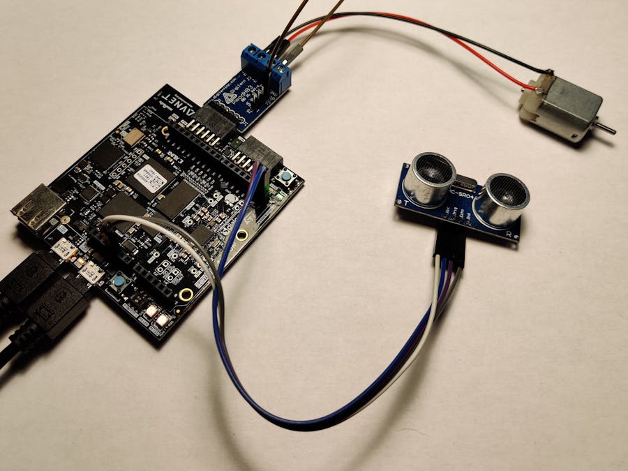
After following the 'Mini but Mighty: Motor Control Live Build with the MiniZed' by Adam Taylor, I started thinking about a useful upgrade to this project. When I searched through my sensors, I stumbled upon the well known HC_SR04 ultrasonic distance sensor. The distance sensor would be a useful upgrade if we would for example use the motor to move a toy car. When the sensor detects an object it can make the motor go slower and slower as it comes closer to the object, until it eventually stops.
If we want to make an application in Vitis for the HC_SR04, we need to be able to drive the hardware. For this purpose we have to design a component in VHDL code first. We will then make a custom AXI IP we can add in a block design and connect to the ZYNQ processor. When all this is done, we can export the hardware design and start making an application in Vitis and run it on the MiniZed.
If you want to know how the HC-SR04 works precisely, you can check out this website. It has a clear overview of the hardware, how it works, how you should wire it and examples for the Arduino.
VHDL code for HC_SR04Let's start with the VHDL design. I didn't write the VHDL code myself, but received it from my teacher Vincent Claes and just modified it to my needs. It may be worth checking him out on GitHub since he has a lot of repositories on a variety of topics.
In this tutorial you can find a gallery of screenshots per topic. The caption of each screenshots explains the steps you have to take, but I've also listed them beneath the galleries for a clear overview.
1. Click Create Project
2. Click Next
3. Choose a project name and folder location
Note: Vivado doesn't handle spaces very well, so it's best to not have any in the file path or title. Also don't start your naming with numbers or special characters.
4. Choose RTL Project and click Next
5. We will add sources later, so click Next
6. We don't need Constraints at this time, so click Next
7. Look for the MiniZed under the Boards tab and click on it. Click Next
8. Click Finish, to create a new project
9. Click on the blue plus sign under Sources
10. Choose add or create design sources and click Next
11. Click Create File
12. Give the VHDL file a meaningful title and click OK
13. Click Create File
14. In this step you can define the ports that will be used in the VHDL module. Since we will be copying our code, it's not needed to do it manually. Click OK
15. Click Yes
16. Double-click on the name of the created file to open the editor
17. Copy the code into the file
Note: Don't forget to change the name of the module if you've chosen another name.Note:You can enlarge the code editor by double-clicking on the title. Another double-click will revert it back.
library IEEE;
use IEEE.STD_LOGIC_1164.ALL;
use IEEE.NUMERIC_STD.ALL;

entity HC_SR04 is
    Port ( clk : in  STD_LOGIC;
        trigger : out STD_LOGIC;
        echo : in  STD_LOGIC;
        sonar_out   : out STD_LOGIC_VECTOR (15 downto 0));
end HC_SR04;

architecture Behavioral of HC_SR04 is
    signal count            : unsigned(16 downto 0) := (others => '0');
    signal centimeters      : unsigned(15 downto 0) := (others => '0');
    signal echo_last        : std_logic := '0';
    signal echo_synced      : std_logic := '0';
    signal echo_unsynced    : std_logic := '0';
    signal waiting          : std_logic := '0';
begin

process(clk)
begin
    if rising_edge(clk) then
        if waiting = '0' then
            if count = 1000 then -- Assumes 100MHz
                -- After 10µs then go into waiting mode
                trigger <= '0';
                waiting    <= '1';
                count       <= (others => '0');
            else
                trigger <= '1';
                count <= count+1;
            end if;
        elsif echo_last = '0' and echo_synced = '1' then
            -- Seen rising edge - start count
            count       <= (others => '0');
            centimeters <= (others => '0');
        elsif echo_last = '1' and echo_synced = '0' then
            -- Seen falling edge, so capture count
            sonar_out <= std_logic_vector(centimeters);
        elsif count = 2900*2 -1 then
            -- advance the counter
            centimeters <= centimeters + 1;
            count <= (others => '0');
            if centimeters = 3448 then
                -- time out - send another pulse
                waiting <= '0';
            end if;
        else
            count <= count + 1;
        end if;
        echo_last     <= echo_synced;
        echo_synced   <= echo_unsynced;
        echo_unsynced <= echo;
    end if;
end process;
end Behavioral;
18. When you are ready with the code, we need to run a synthesis to check for errors. Click on the green triangle and choose Run Synthesis or simply press F11
19. In this menu we can choose how many processor cores (jobs) we want to dedicate to run the synthesis. The number of cores will depend on the CPU of your computer. The more cores you use, the faster the synthesis will be done. Click OK
20. If you've done everything correctly, you will see the following message. Click Cancel to close this window
Creating custom IP for HC_SR04To add the HC_SR04 to our block design, we need to design a custom AXI IP. The steps below will explain how to do that. If you want/need additional information about creating and packaging custom IPs, I can recommend you the user guide by Xilinx.
1. Under Tools, click on Create and Package New IP...
2. Click Next
3. Choose to Create AXI4 Peripheral and click Next
4. Choose a name and location for the IP. Again, watch out for spaces and special characters
5. The Number of Registers we actually need is 1, but I always leave these settings by default
6. The next step is to edit the IP. Choose Edit IP and click Finish
7. When the IP project opens we can see 2 nested sources have been created
8. Open the top module and go to line number 19. Add the ports except for the sonar_out, because this will not be a physical pin
clk         : in STD_LOGIC;
echo        : in STD_LOGIC;
trigger     : out STD_LOGIC;
9. Open the sub module and create the same ports on line number 19. Because these ports will only be used internally, I gave them other names to mark the difference
clk_internal        : in STD_LOGIC;
echo_internal       : in STD_LOGIC;
trigger_internal    : out STD_LOGIC;
10. Still in the sub module we will define a signal to be used as the sonar_out on line 102. I also gave this a different name to mark the difference
signal sonar_out_internal : STD_LOGIC_VECTOR(C_S_AXI_DATA_WIDTH-1 downto 0);11. Back in the top module we will need to add the internal ports as well. This can be done on line number 60
clk_internal        : in STD_LOGIC;
echo_internal       : in STD_LOGIC;
trigger_internal    : out STD_LOGIC;
12. Still in the top module we need to map the ports that will be used externally to the internal ports. This can be done on line number 96
clk_internal => clk,
echo_internal => echo,
trigger_internal => trigger,
13. Back in the sub module we will add the HC_SR04 entity that we’ve created earlier as a component. This can be done on line number 125
component HC_SR04
Port (clk       : in STD_LOGIC;
    echo      : in STD_LOGIC;
    trigger   : out STD_LOGIC;
    sonar_out : out STD_LOGIC_VECTOR(15 downto 0));
end component;
14. Still in the sub module, we scroll down to line number 359. Here we will change slv_reg0 to our sonar_out_internal signal. Do the same on line number 366.
process (sonar_out_internal, slv_reg1, slv_reg2, slv_reg3, axi_araddr, S_AXI_ARESETN, slv_reg_rden)

reg_data_out <= sonar_out_internal;
15. Still in the sub module on line number 398, we will need to map the internal ports to the ports of the component we created
axi_HC_SR04 : HC_SR04
    Port map (  clk         => clk_internal,
                trigger     => trigger_internal,
                echo        => echo_internal,
                sonar_out   => sonar_out_internal(15 downto 0));
16. When this is done, you will note that there is a third design source with a little question mark next to its name. This means we need to add the design source from which we’ve created the component. To do this, right click in the sources window and choose Add Sources…, or simply click the blue plus sign
17. Choose to add or create design sources. Click Next
18. Click Add Files
19. Navigate to the.vhd file of our first project. This can be found under projectname/projectname.srcs/sources_1/new. Click OK
20. Make sure that the checkbox next to Copy sources into IP Directory is ticked. Click Finish
21. If you’ve made no mistakes, there will be a blue circle next to the component name. Now we are almost ready to package the IP
22. Click on the Package IP – Ultrasonic_IP tab. You will notice that under Packaging Steps not all the steps have a green tick sign next to them. We will fix this
23. Click on File Groups. Under File Groups, click on Merge changes from File Groups Wizard. The tick sign will now appear
24. Next click on Customization Parameters and do the same. The green tick will now appear not only here but also next to Customization GUI
25. Next click on Ports and Interfaces. You can see a yellow circle on the page which means that there are warnings. These are not critical, we can just ignore them
26. Click on Review and Package next. Click on the button Re-Package IP on the bottom of the page. This will package the IP
27. When everything went correctly, you will get a dialog telling you that the packaging has finished successfully. Click Yes to close the project
Adding HC_SR04 IP to Block Diagram (Hardware Build)The next step is to create a new project to design the hardware. Follow the hardware build steps from Adam Taylor's Mini But Mighty, the MiniZed and Vitis for Motor Control to start.
1. If you've followed Adam's guide correctly, your block design should resemble the one in the screenshot. To add the custom HC_SR04 IP, click on Settings in the upper left corner
2. Under IP > Repository, click on the blue plus sign
3. Navigate to the folder where you've stored your custom IP
4. A window will open that will list all the stored IPs in that folder. Click OK
5. The folder will now be visible under IP Repositories. Click OK
6. Back on the block design, click on the blue plus sign. Look for the custom IP in the list and double-click it
7. Once the custom IP is added on the block design, we need to change some settings in the ZYNQ processor. Double-click on it to open the settings
8. Open the PS_PL Configuration tab and make sure to tick the checkbox next to M AXI GP0 interface. You can find this under AXI Non Secure Enablement > GP Master AXI Interface
9. Go to the Clock Configuration tab next and note which clock has a frequency of 100 MHz. This will be the clock to which we will connect the HC_SR04 later. Click OK to close the windows
10. Next we will make the trigger and echo ports of the HC_SR04 external. To do this, highlight the name of the port by clicking on it, followed by a right click on it. Click on Make External in the opened menu
11. We can now run the connection automation by clicking on it in the green bar
12. Make sure to tick all the checkboxes in the opened window and that the clock will be connected to the right one. Click on the clock. Under Clock Source we can choose to which clock it will connect. Choose the clock with a frequency of 100 MHz. Click OK
13. Your result should look similar to the screenshot, if not you can click on the round arrow sign. This will move the blocks on your block design around to make it more presentable and easier to read
14. All we need to do now is to add the trigger and echo ports to the constraints file, so they can be linked to the hardware. We will connect the HC_SR04 to the Arduino compatible headers. We will connect the trigger with IO0 and the echo with IO1
set_property PACKAGE_PIN R8  [get_ports {trigger_0}];   # "R8.ARDUINO_IO0"
set_property PACKAGE_PIN P8  [get_ports {echo_0}];      # "P8.ARDUINO_IO1"
set_property PACKAGE_PIN M15 [get_ports {TTC0_WAVE0_OUT_0}];
set_property PACKAGE_PIN L15 [get_ports {GPIO_O_0}];

set_property IOSTANDARD LVCMOS33 [get_ports trigger_0]
set_property IOSTANDARD LVCMOS33 [get_ports echo_0]
set_property IOSTANDARD LVCMOS33 [get_ports TTC0_WAVE0_OUT_0]
set_property IOSTANDARD LVCMOS33 [get_ports GPIO_O_0]
15. To make sure we've made no mistakes in the block design, we click on the checkbox sign in the toolbar. This will validate the design
16. It will run a validation
17. And confirm everything is fine. Click OK
18. Next we will generate a bit stream to compile the design. Click on the green symbol next to the synthesis button
19. Click OK
20. Choose the number of jobs you want to run and click OK
21. The bit stream generation will now run, depending on your CPU this could take some time. After a while you (hopefully) will get the message that the bit stream generation was successful. Click Cancel to close this window
22. Once the bit stream is available, the next and last step is to export the XSA to use it in Vitis. Click on File > Export > Export Hardware
23. Tick the Include bitstream checkbox and click OK. The XSA will be saved in the root folder of your project
Programming HC_SR04 in Vitis (Software Build)The next step is to create an application project in Vitis to drive the hardware. Follow the software build steps from Adam Taylor's Mini But Mighty, the MiniZed and Vitis for Motor Control, but use the C code below instead.
I've changed Adam's code so that the HC_SR04 will control the speed of the motor instead of the serial input.
To be able to use the custom IP we need to add the following header files.
#include "xil_io.h"
#include "xparameters.h"
#include "Ultrasonic_IP.h"
Reading the distance from the HC_SR04 is pretty simple. We just need to define a variable to store the value in and we need to use the ULTRASONIC_IP_mReadReg function which can be found in the Ultrasonic_IP.h. This function needs only two arguments: the base address of the custom IP and the offset of slv_reg0. Both of these can be found in the xparameters.h.
u32 distance;
distance = ULTRASONIC_IP_mReadReg(XPAR_ULTRASONIC_IP_0_S00_AXI_BASEADDR, ULTRASONIC_IP_S00_AXI_SLV_REG0_OFFSET);
To set the speed of the motor, I compare the distance to certain set values. If the distance is within a specific range the value of the DutyCycle will change. The DutyCycle of the PWM will only change if the value of the DutyCycle actually changes. Hence the comparison between DutyCycle and PrevDutyCycle.
if (distance > 0 && distance < 3) {
    DutyCycle = 0;
} else if (distance < 6) {
    DutyCycle = 25;
} else if (distance < 9) {
    DutyCycle = 33;
} else if (distance < 12) {
    DutyCycle = 50;
} else if (distance < 15) {
    DutyCycle = 66;
} else if (distance < 18) {
    DutyCycle = 75;
} else if (distance < 21) {
    DutyCycle = 100;
} else {
    DutyCycle = 0;
}

if (DutyCycle != PrevDutyCycle) {
    set_pwm(DutyCycle);
}

PrevDutyCycle = DutyCycle;
sleep(0.5);

printf("Distance: %u cm\n\r", distance);
printf("DutyCycle: %u\n\r\n\r", DutyCycle);
The complete code.
#include <stdio.h>
#include "platform.h"
#include "xil_printf.h"
#include "xgpiops.h"
#include "sleep.h"
#include "xil_exception.h"
#include "xttcps.h"
#include "xscugic.h"
#include "xil_io.h"
#include "xparameters.h"
#include "Ultrasonic_IP.h"

#define GPIO_DEVICE_ID  	XPAR_XGPIOPS_0_DEVICE_ID
#define INTC_DEVICE_ID		XPAR_SCUGIC_0_DEVICE_ID
#define	TICK_TIMER_FREQ_HZ	100
#define TTC_TICK_DEVICE_ID	XPAR_XTTCPS_0_DEVICE_ID
#define TTC_TICK_INTR_ID	XPAR_XTTCPS_0_INTR

static void TickHandler(void *CallBackRef);
int SetupTicker(XTtcPs *TtcPsInst,u16 DeviceID,u16 TtcTickIntrID,XScuGic *InterruptController);
static int SetupInterruptSystem(u16 IntcDeviceID,XScuGic *IntcInstancePtr);
int SetupTimer(u16 DeviceID,XTtcPs *TtcPsInst);
void set_pwm(u32 cycle);
void display_menu();

typedef struct {
    u32 OutputHz;	/* Output frequency */
    XInterval Interval;	/* Interval value */
    u8 Prescaler;	/* Prescaler value */
    u16 Options;	/* Option settings */
} TmrCntrSetup;

XGpioPs Gpio;
XGpioPs_Config *ConfigPtr;
XTtcPs_Config *TtcConfig;
XTtcPs ttcTimer;
TmrCntrSetup *TimerSetup;
XScuGic InterruptController;  	/* Interrupt controller instance */
XTtcPs TtcPsInst;
u32 MatchValue;

static TmrCntrSetup SettingsTable={TICK_TIMER_FREQ_HZ, 0, 0, 0};

int main()
{
    u8 DutyCycle;
    u8 PrevDutyCycle;
    u32 distance;

    init_platform();

    TmrCntrSetup SettingsTable = {TICK_TIMER_FREQ_HZ, 0, 0, 0};
    ConfigPtr = XGpioPs_LookupConfig(GPIO_DEVICE_ID);
    XGpioPs_CfgInitialize(&Gpio, ConfigPtr,ConfigPtr->BaseAddr);
        XGpioPs_SetDirectionPin(&Gpio, 54, 1);
    XGpioPs_SetOutputEnablePin(&Gpio, 54, 1);
    XGpioPs_WritePin(&Gpio, 54, 0x1);
    printf("DC Motor Control With HC_SR04\n\r");
    SetupInterruptSystem(INTC_DEVICE_ID, &InterruptController);
    SetupTicker(&ttcTimer,TTC_TICK_DEVICE_ID,TTC_TICK_INTR_ID,&InterruptController);
    while(1) {
        distance = ULTRASONIC_IP_mReadReg(XPAR_ULTRASONIC_IP_0_S00_AXI_BASEADDR, ULTRASONIC_IP_S00_AXI_SLV_REG0_OFFSET);

        if (distance > 0 && distance < 3) {
            DutyCycle = 0;
        } else if (distance < 6) {
            DutyCycle = 25;
        } else if (distance < 9) {
            DutyCycle = 33;
        } else if (distance < 12) {
            DutyCycle = 50;
        } else if (distance < 15) {
            DutyCycle = 66;
        } else if (distance < 18) {
            DutyCycle = 75;
        } else if (distance < 21) {
            DutyCycle = 100;
        } else {
            DutyCycle = 0;
        }

        if (DutyCycle != PrevDutyCycle) {
            set_pwm(DutyCycle);
        }

        PrevDutyCycle = DutyCycle;
        sleep(0.5);

        printf("Distance: %u cm\n\r", distance);
        printf("DutyCycle: %u\n\r\n\r", DutyCycle);
    }

    cleanup_platform();
    return 0;
}

void set_pwm(u32 cycle)
{
    u32 MatchValue;
    MatchValue = (TimerSetup->Interval * cycle) / 100;
    XTtcPs_SetMatchValue(&ttcTimer, 0, MatchValue);
}

int SetupTicker(XTtcPs *TtcPsInst,u16 DeviceID,u16 TtcTickIntrID,XScuGic *InterruptController)
{
    int Status;
    TmrCntrSetup *TimerSetup;
    XTtcPs *TtcPsTick;

    TimerSetup = &SettingsTable;
    TimerSetup->Options |= (XTTCPS_OPTION_INTERVAL_MODE |
        XTTCPS_OPTION_MATCH_MODE | XTTCPS_OPTION_WAVE_POLARITY);
    Status = SetupTimer(DeviceID,TtcPsInst);

    if(Status != XST_SUCCESS) {
        return Status;
    }

    TtcPsTick = TtcPsInst;
    Status = XScuGic_Connect(InterruptController, TtcTickIntrID,
        (Xil_InterruptHandler)TickHandler, (void *)TtcPsTick);

    if (Status != XST_SUCCESS) {
        return XST_FAILURE;
    }

    XScuGic_Enable(InterruptController, TtcTickIntrID);
    XTtcPs_EnableInterrupts(TtcPsTick, XTTCPS_IXR_INTERVAL_MASK);
    XTtcPs_Start(TtcPsTick);

    return Status;
}

static int SetupInterruptSystem(u16 IntcDeviceID,XScuGic *IntcInstancePtr)
{
    int Status;
    XScuGic_Config *IntcConfig;
    IntcConfig = XScuGic_LookupConfig(IntcDeviceID);

    if (NULL == IntcConfig) {
        return XST_FAILURE;
    }

    Status = XScuGic_CfgInitialize(IntcInstancePtr, IntcConfig,
        IntcConfig->CpuBaseAddress);

    if (Status != XST_SUCCESS) {
        return XST_FAILURE;
    }

    Xil_ExceptionRegisterHandler(XIL_EXCEPTION_ID_IRQ_INT,
        (Xil_ExceptionHandler) XScuGic_InterruptHandler,
        IntcInstancePtr);
    Xil_ExceptionEnable();

    return XST_SUCCESS;
}

int SetupTimer(u16 DeviceID,XTtcPs *TtcPsInst)
{
    int Status;
    XTtcPs_Config *Config;
    XTtcPs *Timer;
    TmrCntrSetup *TimerSetup;

    TimerSetup = &SettingsTable;
    Timer = TtcPsInst;
    Config = XTtcPs_LookupConfig(DeviceID);

    if (NULL == Config) {
        return XST_FAILURE;
    }

    Status = XTtcPs_CfgInitialize(Timer, Config, Config->BaseAddress);

    if (Status != XST_SUCCESS) {
        return XST_FAILURE;
    }

    XTtcPs_SetOptions(Timer, TimerSetup->Options);
    XTtcPs_CalcIntervalFromFreq(Timer, TimerSetup->OutputHz,
        &(TimerSetup->Interval), &(TimerSetup->Prescaler));
    XTtcPs_SetInterval(Timer, TimerSetup->Interval);
    XTtcPs_SetPrescaler(Timer, TimerSetup->Prescaler);

return XST_SUCCESS;
}

static void TickHandler(void *CallBackRef)
{
    u32 StatusEvent;
    //Read the interrupt status, then write it back to clear the interrupt.
    StatusEvent = XTtcPs_GetInterruptStatus((XTtcPs *)CallBackRef);
    XTtcPs_ClearInterruptStatus((XTtcPs *)CallBackRef, StatusEvent);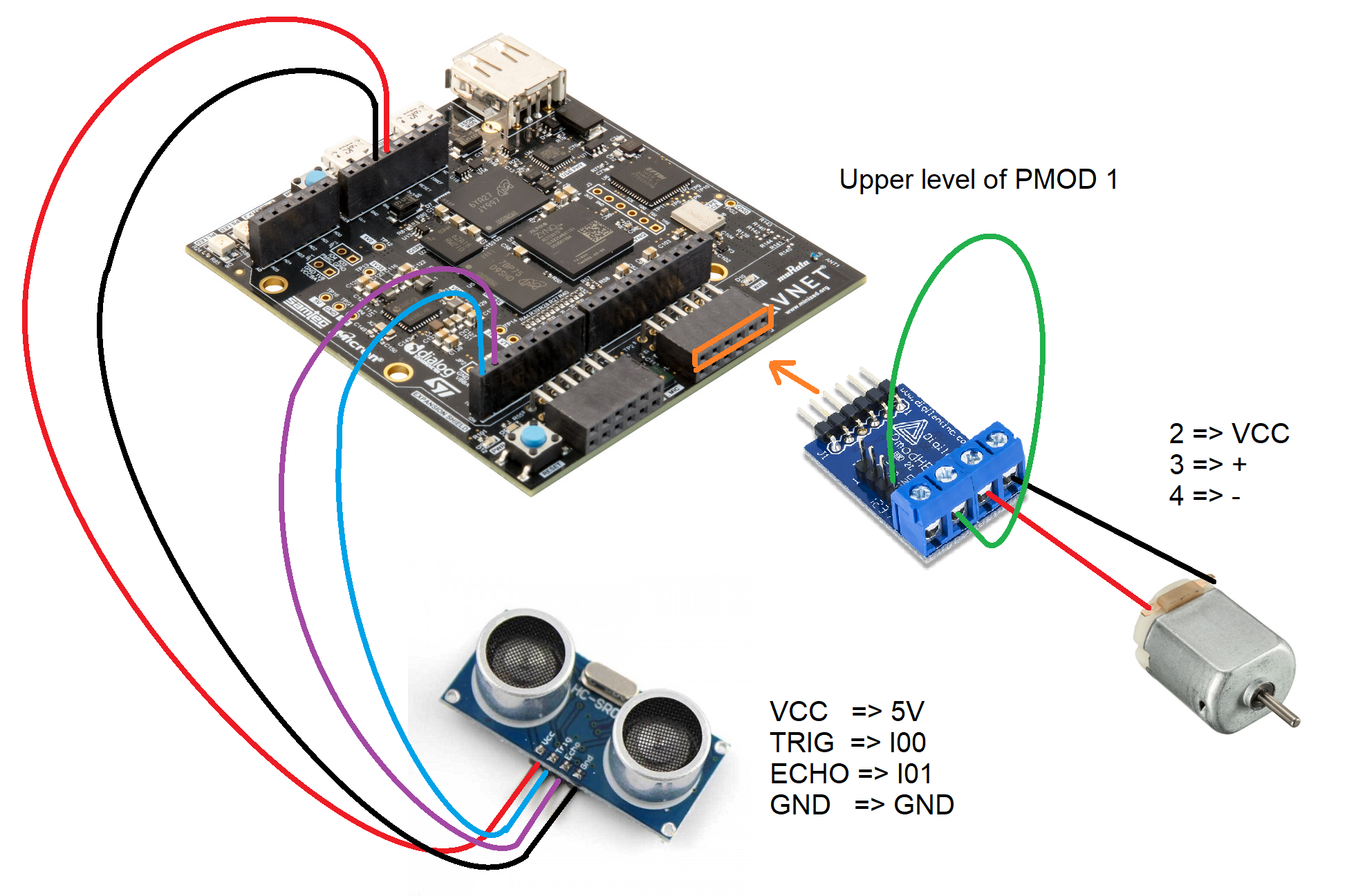
}PMOD module
- Connect the VCC pin to the 2nd header
- Connect the 3rd header to the positive side of the motor
- Connect the 4th header to the negative side of the motor
MiniZED
- Connect the PMOD module to the upper row of PMOD1. Make sure that the USB cables are not connected when you do this.
- Connect the Vcc of the HC_SR04 to the 5V pin
- Connect the trig of the HC_SR04 to the IO0 pin
- Connect the echo of the HC_SR04 to the IO1 pin
- Connect the Gnd of the HC_SR04 to one of the Gnd pins
When everything is connected on the board you can connect the micro USB cables between the MiniZed and the computer.
When you run the application it is best to use a terminal emulator to actually see the output of the MiniZed.
1. When you open Tera Term you have to open a new connection. Select Serial at the bottom and select the right COM Port for the MiniZed. This can be found through the device manager (in Windows)
2. At the top click on Setup > Serial port...
3. The MiniZed has a default baud rate of 115200, so make sure this setting is right. Click on New setting if you made any adjustments
4. If you run the application on the MiniZed through Vitis, you should be able to see the output in the screenshot
DemoThis demo shows how the speed changes when the HC_SR04 is further away from the desk.
Note: sound is required.


Comments