



Hardware components | ||||||
| × | 1 | ||||
| × | 1 | ||||
| × | 1 | ||||
| × | 1 | ||||
| × | 1 | ||||
| × | 1 | ||||
| × | 1 | ||||
| × | 1 | ||||
| × | 1 | ||||
Hand tools and fabrication machines | ||||||
 |
| |||||
 |
| |||||
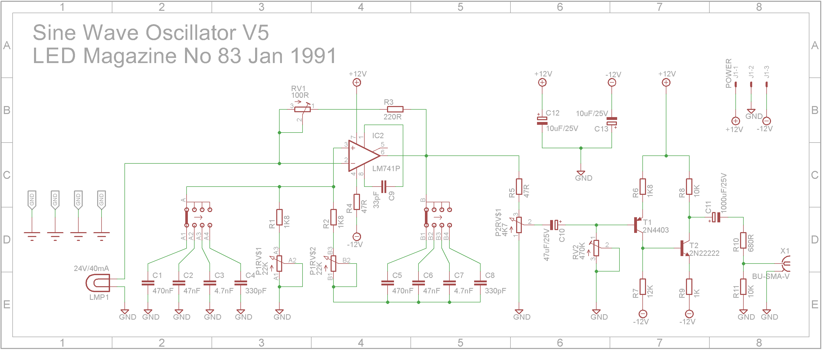
Back in January 1991, a sine wave oscillator appeared in LED Magazine. (A French publication - article and English translation attached). It is a Wien Bridge oscillator that provides a good quality Sine wave that covers the audio range of frequencies. (20Hz to 20kHz)
(reproduced from geeksforgeeks website)
The Wien Bridge Oscillator is a phase shift Oscillator that generates a sine wave. It is a two-stage Resistor Capacitor coupled amplifier circuit. It has good stability at its resonant frequency, low distortion and is exceptionally simple to tune.
In the Wien Bridge Network shown below, one branch has resistor(R1) and capacitor (C1 ) components are connected in series and the other branch has the Resistor (R2 ) and Capacitor (C2 ) are in parallel along with the resistors R3 and R4.
The Op-amp is required to function as a non-inverting amplifier in the Wien-Bridge network as the Wien bridge circuit provides zero phase-shift. From the circuit, it is clear that the output voltage is given back to both inverting and non-inverting input terminals. At resonant frequency, the voltages applied to the inverting will be equal and voltages applied to the non-inverting terminals will be in-phase with each other. Due to the restriction by the open-loop gain, these kind of Operational-Amplifier-based Wien Bridge Oscillators cannot operate above 1 MHz. The voltage gain of the amplifier needs to be more than 3 to start oscillations and equal to 3 to sustain them i.e (Av≥ 3).
The circuit above shows the Wien Bridge Oscillator using 741 operational amplifier. It has Resistor R1 and Capacitor C1 are in series connected to Non inverting terminal of IC 741 at terminal (3), similarly Resistor R2 and Capacitor C2 are in parallel connected to Non inverting terminal of IC 741 at terminal (3). Here Resistor R3 is a variable Resistor which is connected to Inverting terminal at terminal (2) and output of op- amp at terminal (6).
At low frequencies, the reactance of the capacitors C1 and C2 will become very high and the output voltage V0 will remain at zero and called as 'lag circuit', as the capacitor C1 will act as an open circuit. In this circuit, at high frequencies, the reactance of the capacitors C1 and C2 will be much less due to which the Output voltage V0 will become zero then the Resistor R2 will be shorted due to the capacitor C2 and called as 'lead circuit'.
As there is a lead-lag circuit, the circuit doesn't provide any phase shift at Oscillating frequency, so non-inverting Amplifier is used.
As op-amp is operated in the non-inverting configuration the voltage gain is shown below,
Vout / Vin = 1 + R3 / R4 = 3
The STL files for this project are attached. All printing is done using a 0.2mm layer height. You may need to orientate some of the files on the build plate before printing.
When printing "Sine wave generator V1 - Text.stl", change to a contrasting filament color at the start of layer 4. After printing, add double sided tape to the back of the print and stick it to "Sine wave generator V1 - Front.stl".
When printing "Sine wave generator V1 - Knobs.stl", change to a contrasting filament color at the start of layer 61.
Add M3 3x4.2 brass insert nuts to the tabs on "Sine wave generator V1 - Bottom.stl" and "Sine wave generator V1 - Top.stl".
Add M3 3x4.2 brass insert nuts to the power supply studs on "Sine wave generator V1 - Bottom.stl"
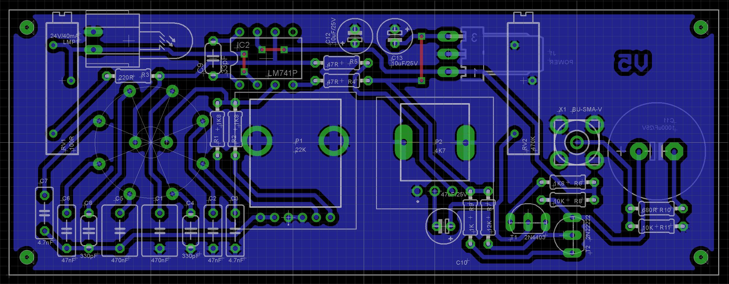
I have included the Eagle files in case you want to get the board commercially made or do as I did and make it yourself. I used the Toner method.
Add the links if your board is single-sided.
Add the resistors next followed by the 741 IC.
Add the capacitors, trimpots and transistors.
Add the SR16 rotary switch, RK1114GH & RV09 potentiometers and SMA socket.
Add the 24V 40mA bulb to the copper-side of the PCB. Use a small piece of double-sided tape to hold it in place. Solder wires to the bulb's terminals and solder the other ends to the PCB.
Add the 1000uF/25V to the copper-side of the PCB. Use a small piece of double-sided tape to hold it in place.
Add a 3-pin KF2510 to the copper-side of the PCB.
Screw the PCB to the front panel using 4x M2 4mm screws.
Add the rocker switch to the front panel
Screw in the SM-FLA17A 17W positive and negative two switching power supply module using 4 x M3 4mm screws.
Wire up modules and power components. I purchased a 3.96mm JST kit for the connections to the SM-FLA17A power module. The power switch uses 4.8mm spade connectors. The front PCB power connector uses a 2.54mm JST connector.
Screw on top clam-shell using 4 x M3 6mm black hex screws.
The Wien bridge oscillator provides a high quality sine wave with low distortion. The final unit looks professional when sitting on a workbench shelf. For audio work, it is more than adequate.





Comments