



Hardware components | ||||||
| × | 4 | ||||
| × | 1 | ||||
| × | 1 | ||||
| × | 1 | ||||
| × | 1 | ||||
| × | 1 | ||||
Hand tools and fabrication machines | ||||||
 |
| |||||
 |
| |||||
Back in February 1983, a function generator appeared in Popular Electronics magazine that allowed the output frequency to be set using thumbwheel switches on the front panel.
In 1983 this was such a novel approach that I wanted to build one but the parts even back then were expensive and hard to obtain. Unfortunately some of the parts are now obsolete and just not available so copying the original design is no longer possible. This build keeps as much of the original design as possible and only deviates to get around any unavailable parts.
The design is based on two phase locked loops.
A phase-locked loop (PLL) is an electronic feedback control system that generates an output signal matching the phase and frequency of an input reference signal. Its three primary components are a phase detector, a loop filter, and a voltage-controlled oscillator.
Core Components
- Phase Detector: Compares the input signal phase with the oscillator's feedback phase and outputs an error voltage proportional to their difference.
- Loop Filter: Smooths the error voltage into a steady control signal by removing high-frequency noise.
- Voltage-Controlled Oscillator (VCO): Adjusts its output frequency up or down based on the control voltage until synchronization is achieved.
How It Works
- Free Running: The VCO operates at its baseline center frequency when no input reference is applied.
- Capture: The system detects an incoming reference signal and shifts the VCO frequency to approach it.
- Lock/Tracking: The feedback loop continuously minimizes phase error until the output frequency and phase lock precisely onto the input reference.
The first part of the circuit has a crystal controlled oscillator (IC1) that generates a 100Hz reference signal. This is feed to the Phase Locked Loop (IC2 Pin 14). R20 & C5 determine the frequency of the Voltage Controlled Oscillator (VCO). The output of the divider feedback circuit is compared by a phase comparator with the 100Hz input signal and the output appears at pin 13 of IC2. This is then fed into a low pass filter consisting of R18 & C6 with its output controlling the frequency of the VCO via pin 9. The output of the VCO is feed through a Programmable Divide-By-N Counter (IC3) and feed back to the other side of the phase comparator (pin 3).
The output is feed to a dual divide by 10 counter (IC4). A switch determines whether the thumbwheel switches are switching between 1Hz to 9,999 Hz (10kHz position) or 10 Hz to 99,990 Hz (100kHz position).
MM5369EST Oscillator/Divider ICThe MM5369 17 Stage Oscillator/Divider (IC1) produces a 60 Hz signal when used with a 3,579,545 Hz quartz crystal. The schematic however calls for the EST version of this chip and produces a 100 Hz signal using the same crystal frequency. I could not find a source for this variant of the MM5369. The schematic was modified to provide an alternative 100 Hz crystal controlled signal.
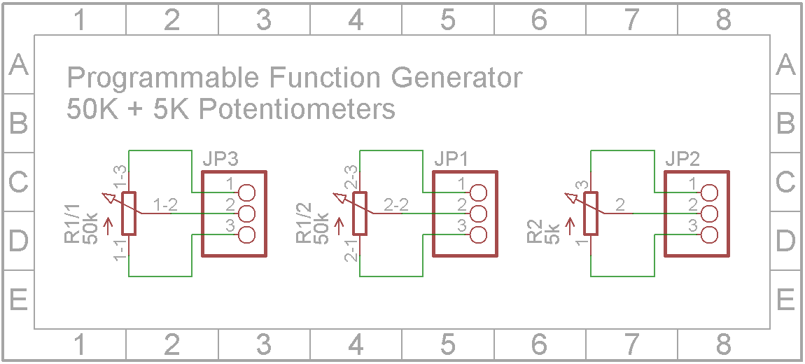
The other issue I ran into when sourcing the components was that the circuit called for a dual potentiometer where one part was 50k and the other 5k. This component I couldn't find anywhere so I made one.
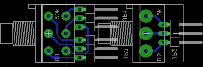
It uses a dual 50k potentiometer. The dual potentiometers have a open part in the back allowing for a extra shaft. A 3D printed shaft extender is inserted and this allows a single 5k potentiometer to be connected to the other end of the shaft. The whole assembly is held together by a custom designed printed circuit board.
When assembling the dual pot, make sure both pots are turned anticlockwise to their respective end-stops before inserting the shaft connector. Ony solder the back potentiometer after the shaft extender is inserted and you have verified it is in the correct position.
3D printingThe STL files for the case are attached. All printing is done using a 0.2mm layer height. You may need to orientate the parts on the build plate before slicing.
When printing "Programmable Function Generator V1 - Text.stl", switch to a filament of a contrasting color at the start of layer 4.
Print "Programmable Function Generator V1 - Front.stl" with supports. After printing, remove the supports and add the 50k + 5k potentiometer assembly and rotary switch to their respective holes. Do not use washers as the nuts need to sit below or flush with the front. Screw on the 10k/100k slide switch using M2 flat head screws.
Place "Programmable Function Generator V1 - Text.stl" on the front of "Programmable Function Generator V1 - Front.stl". The case and other front panel components will hold these two sections together.
Finally add the SMA connector, thumbwheel switches and power rocker switch.
Add 4mm diameter by 3mm high M3 brass inserts into the holes on the tabs for the bottom and top clam-shells.
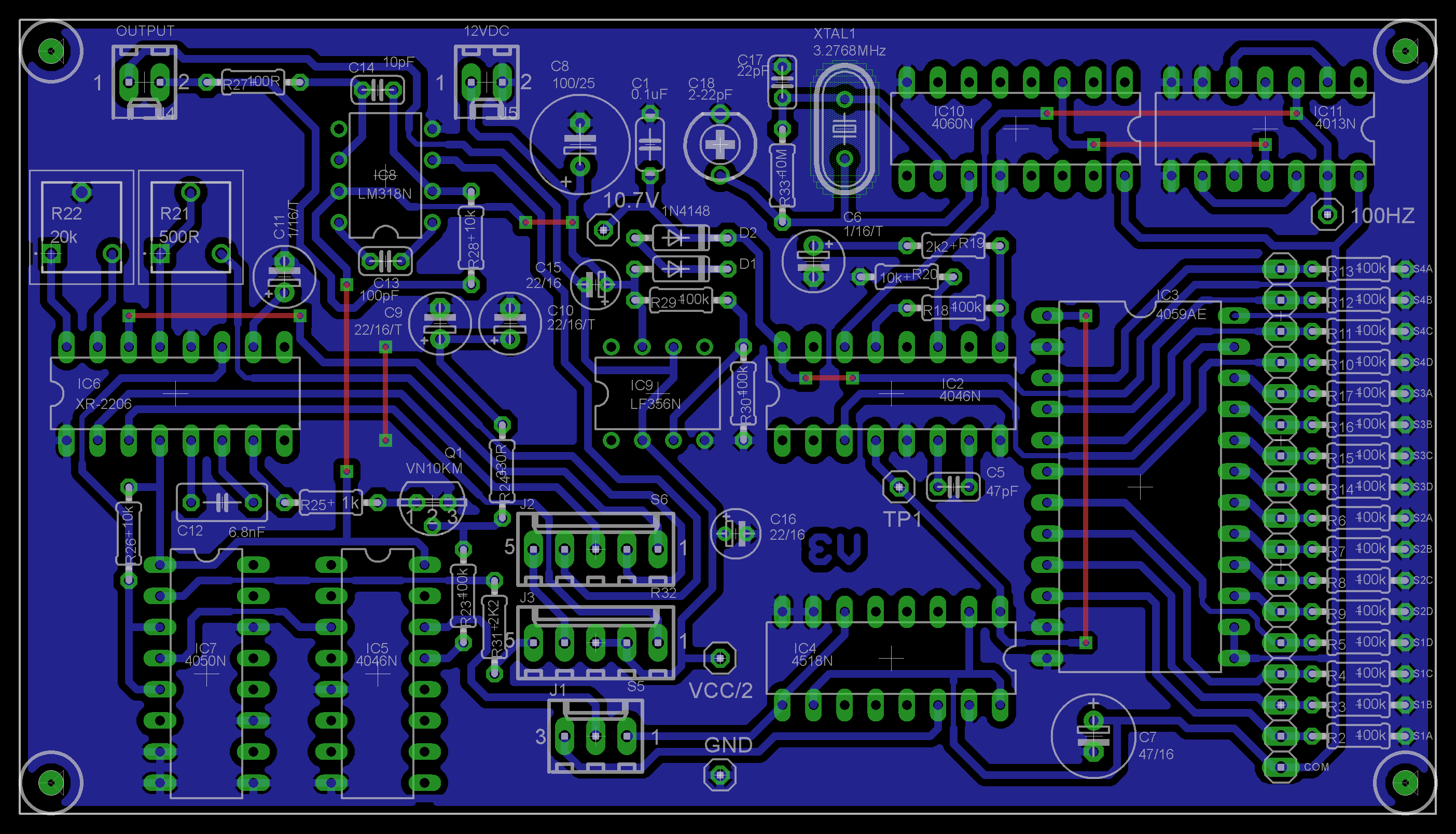
AssemblyI have included the Eagle files in case you want to get the board commercially made or do as I did and make it yourself. I used the Toner method.
Add the links if your board is single-sided.
Add the diodes and resistors.
Add the IC sockets or you can just solder on the ICs.
Add the capacitors, trimpots and transistors.
Add the pin-headers and KF2510 connectors.
Screw the PCB to the front panel using 4 x M2 4mm screws.
Screw in the Javino AC220V to DC 12V Precision Buck Converter 12W 1A power supply module using 4 x M3 4mm screws.
Wire up modules and power components. I purchased a 3.96mm JST kit for the connections to the power module. The power switch uses 4.8mm right-angle spade connectors. The other connectors are 2.54mm KF2510 connectors.
Screw on top clam-shell using 4 x M3 6mm black hex screws.
It has only taken 43 years to finally build this function generator. It's use might be pretty limited these days but it was a challenging and rewarding project.
Discrete electronics without microprocessors is still fun. It's a pity in some-ways that it is a dying art but if you are interested in looking at old electronic magazines, the best source that I have found is https://worldradiohistory.com/





Comments