

Hardware components | ||||||
| × | 1 | ||||
 |
| × | 1 | |||
 |
| × | 1 | |||
 |
| × | 2 | |||
| × | 1 | ||||
| × | 5 | ||||
| × | 1 | ||||
 |
| × | 1 | |||
| × | 4 | ||||
Software apps and online services | ||||||
 |
| |||||
Hand tools and fabrication machines | ||||||
 |
| |||||
 |
| |||||
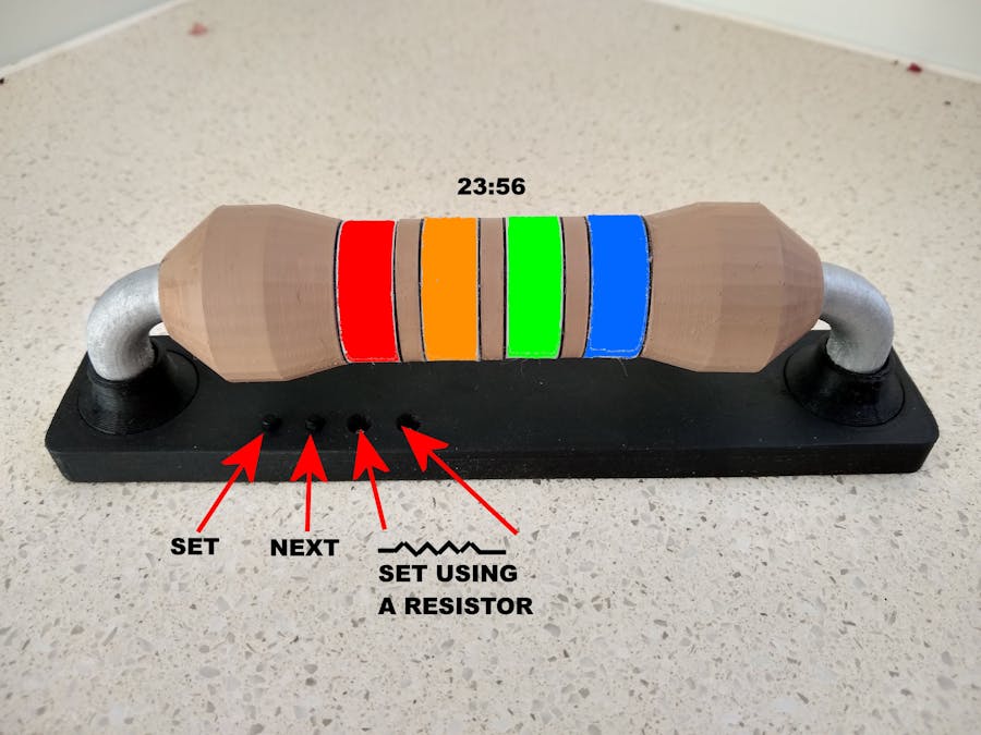
This clock is shaped like a big resistor and shows the time by lighting up the bands with the equivalent resistor color code.
If you don't know your resistor color code, you can use the table below to determine the time.
The clock supports setting the time using a pair of buttons or by reading the value of an actual resistor placed on its two terminals.
The two buttons are SET and NEXT. Pressing the SET button will cause the Hours - Ten and Hours - Units bands to flash. The NEXT button will advance the hours. It will automatically roll around to zero (BLACK - BLACK) after reaching 23 (RED - ORANGE). Pressing the SET button will fix the hours and flash the Minutes - Ten band. The NEXT button will advance the tens of minutes. It will automatically roll around to zero (BLACK) after reaching 5 (GREEN). Pressing the SET button will fix the tens of minutes and flash the Minutes - Units band. The NEXT button will advance the units of minutes. It will automatically roll around to zero (BLACK) after reaching 9 (WHITE). Pressing the SET button again will write the time back to the Real Time Clock (RTC).
To set the time using a resistor, place the resistor on the terminals and press the NEXT button. Values greater than 100,000 ohms are ignored. Any value greater than 2359 ohms will cause the clock to be set to 23:59. Any minute value greater than 59 will cause the clock to be set to 59 minutes. A 390 ohm resistor for example will cause the time to display 03:59.
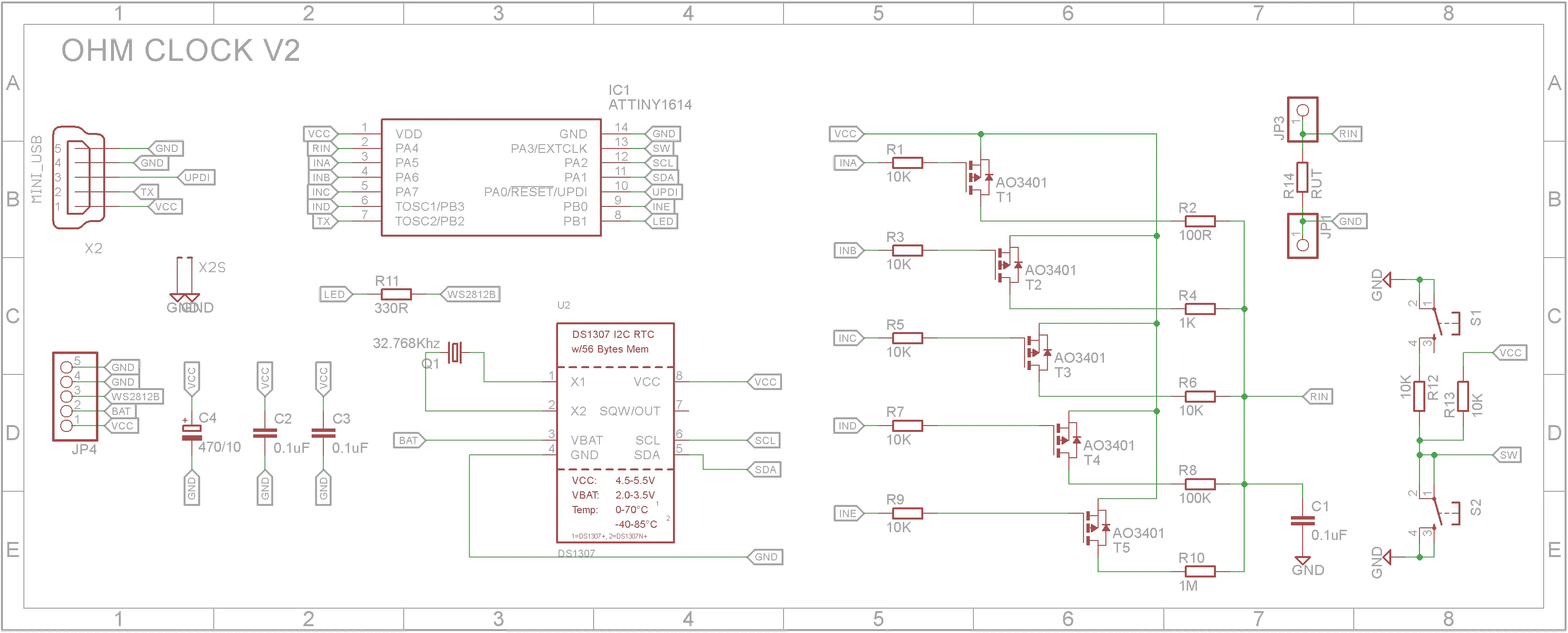
Circuit designThe clock is built around a ATtiny1614 microprocessor. It uses a DS1307 RTC (Real Time Clock) to keep the time even when the clock is not powered. Two tactile buttons are used to manually set the time. The clock also includes a auto-ranging ohm meter so that you can set the time using a resistor. eg a 1000 ohm resistor will set the time to 10:00am where as a 2200 ohm resistor will set the time to 2200 hours or 10:00pm.
The ohm meter uses a analog pin to read the output of a voltage divider using a known resistor and the resistor being measured. It has five ranges and each range is switched by a P-Channel MOSFET.
The STL files have been included. Either take them to a 3D print shop and get them printed or if you have your own 3D printer, run them through your slicing software.
- "Ohm - Band Separator.stl" - 3 off, 0.2mm Layer Height, No supports, WHITE
- "Ohm - Band.stl" - 4 off, 0.2mm Layer Height, No supports, BROWN
- "Ohm - Black Seperator.stl" - 8 off, 0.2mm Layer Height, No supports, BLACK
- "Ohm - End Piece.stl" - 2 off, 0.2mm Layer Height, Supports touching build-plate, BROWN
- "Ohm - Wire.stl" - 2 off, 0.2mm Layer Height, Supports touching build-plate, SILVER
- "Ohm - Mount.stl" - 2 off, 0.2mm Layer Height, No supports, BLACK
- "Ohm - Base.stl" - 1 off, 0.2mm Layer Height, All supports, BLACK
The first step after printing the parts is to add a WS2812B RGB LED to each segment. Originally I used 4 WS2812B RGB 5050 LEDs and soldered wires directly to each pin.
The problem is that the LEDs are easily damaged if too much heat is applied. To simplify the build, my second version used WS2812B mounted on heatsinks.
Wiring still says the same no matter which type of WS2812B LED you choose to use.
Each segment has a black end plate on each end (Ohm - Black Seperator.stl). Use super glue to glue on each end plate.
Test the segment assembly using a WS2812B tester. You can wire up a quick tester using the StrandTest example from the Adafruit_NeoPixel library on an Arduino UNO or similar. I used my home-made WS2812B tester.
Each segment is separated from its neighbor with a separator (Ohm - Band Separator.stl). Use super glue to glue the separator onto one of the segments. Connect the DOUT from the right segment to the DIN of the left segment. Once connected, glue the two segments together.
All the GND wires are connected together and all VCC wires are connected together. You can now glue on the end pieces ("Ohm - End Piece.stl"). Test the completed assembly.
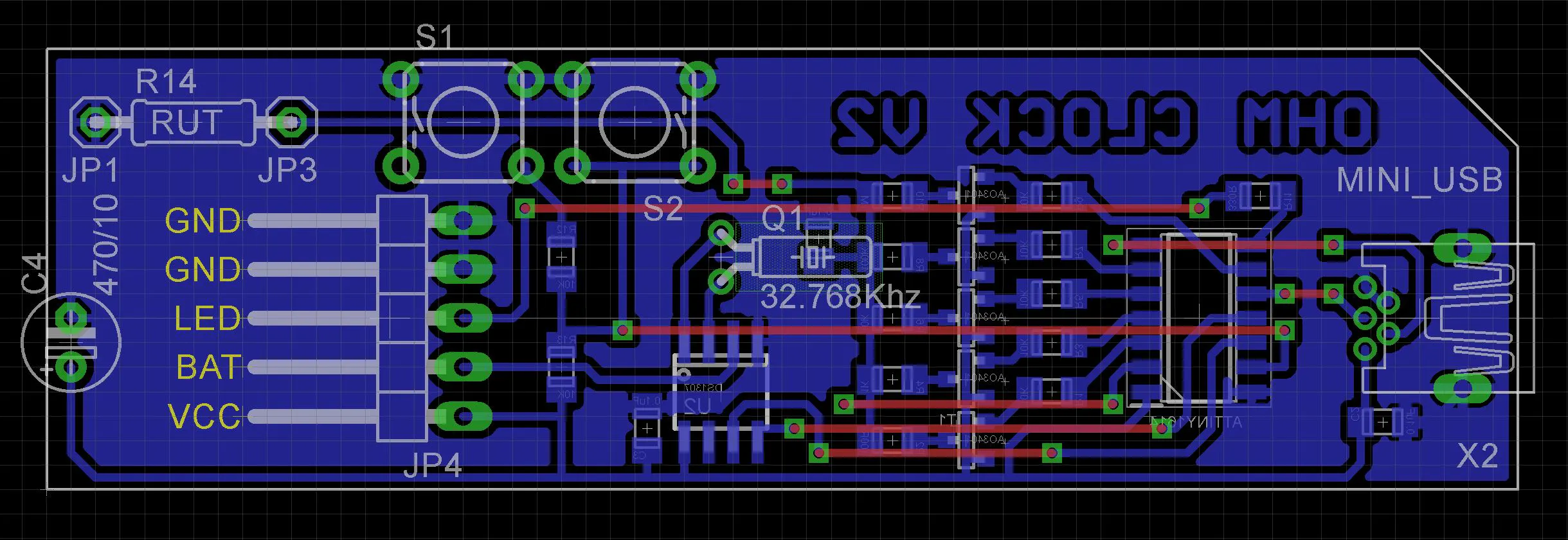
Assembly - Step 5Now it is time to assemble the PCB. As the ATtiny1614 is only available in a SMD package, the PCB uses SMD packages through-out.
I have included the Eagle files in case you want to get the board commercially made or do as I did and make it yourself. I used the Toner method.
Start by adding the SMD components. I find it easier to use solder paste rather than use solder from a reel when soldering SMD components.
Add the links if your board is single sided.
Assembly - Step 6Add top side components to the PCB. Note that the 470uF capacitor sits off the board. I used two machined female header pins to allow an external resistor to set the time.
Before you glue anything else, I would suggest that you upload the code (See next step). With the resistor assembly active, rotate the assembly until the bands are visible. Glue on "Ohm - Wire.stl" to each end of the resistor assembly. Glue the two "Ohm - Mount.stl" mounts to the "Ohm - Base.stl" base. Finally glue the base to the resistor assembly.
Glue on the 2032 SMD battery holder and the PCB with hot glue. You may want to apply hot glue to keep the wiring in place.
Assembly - Step 7The ATtiny1614 is part of the new breed of ATtiny microprocessors. Unlike the earlier series such as the ATtiny85, the new breed use the RESET pin to program the CPU. To program it you need a UPDI programmer. I made one using a Arduino Nano. You can find complete build instructions at Create Your Own UPDI Programmer. It also contains the instructions for adding the megaTinyCore boards to your IDE.
The USB socket provides power to the clock (5V). The UPDI pin of the ATtiny1614 processor is connected the D+ pin on the USB socket. This allows the programming of the ATtiny1614 using a custom cable. USB Mini plugs are available on eBay or you can cut up an old USB Mini cable.
Connect the USB cable from your PC to the Arduino Nano. Open up the Arduino IDE and upload the attached sketch.
ConclusionUnfortunately the RGB LEDs cannot show a full range of colors. Brown is a problematic color along with gray and black. This tends to spoil the overall effect.


Comments