

Hardware components | ||||||
 |
| × | 1 | |||
| × | 1 | ||||
| × | 3 | ||||
| × | 1 | ||||
| × | 4 | ||||
| × | 7 | ||||
| × | 1 | ||||
| × | 1 | ||||
| × | 1 | ||||
| × | 4 | ||||
| × | 1 | ||||
| × | 3 | ||||
| × | 3 | ||||
| × | 1 | ||||
| × | 1 | ||||
 |
| × | 1 | |||
Software apps and online services | ||||||
 |
| |||||
Over the years, I have made a number of projects based around the WS2812B RGB LED. These come as individual LEDs or attached to circular rings and panels just to name a few. Here are just some of my projects that used these LEDs
Neopixel Butterfly (https://www.thingiverse.com/thing:3938405)
Neopixel Xmas Tree (https://www.thingiverse.com/thing:3910914)
Neopixel Mini Cube (https://www.thingiverse.com/thing:4022751)
Hot Glue LED Matrix Lamp (https://www.thingiverse.com/thing:3403301)
CUBE LED with Neopixel panels (https://www.thingiverse.com/make:410209)
PCB Christmas Tree (https://www.thingiverse.com/thing:3973564)
WiFi Grid Clock (https://www.thingiverse.com/thing:3915274)
WeMos Flower Alarm Clock (https://www.thingiverse.com/thing:3986237)
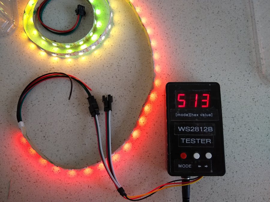
During the building of these projects, it was important to test the LEDs and wiring usually before the software is written or hardware is even finished. So I created a WS2812B Tester which has served be well over the years. Recently I built the Mini Cube which drives 96 WS2812B LEDs off a 120mA/Hr battery. I needed to know what brightness I should set the LEDs to so the current used didn't overload or drain the battery too quickly. I saw Utsav_25's Power Measurement Module for Arduino (https://www.instructables.com/id/DIY-Power-Measurement-Module-for-Arduino/) and decided to incorporate the ammeter part into this updated tester. It has proved very useful and I haven't seen any other tester around that incorporates an ammeter. So with this in mind, others might also find this project useful.
Building the caseThe project uses a cheap 100x60x25mm project box from eBay. It houses a simple printed circuit board. I have included the Eagle files should you wish to get it made commercially or do as I did and make it yourself. I used the Toner method. Once you have the board, tape it to the lid of the box as a template. This allows you to ensure the display and switches align precisely with the board. Carefully drill out the three holes at the center of each button and the 12 holes that hold the 3-digit 7 segment display using a 0.8mm drill.
You can now remove the board and drill out the switch holes with a 6mm drill. Insert the display in the front of the panel and mark around it to get the area that needs to be cut away. I also glued some red perspex from and old VCR to the underside of the front. It really is there primarily for ascetics.
I used a Label Machine to make the labels that are added to the front panel.
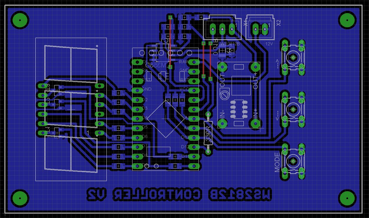
Next make up the board. Start with the SMD components. It is easier to use solder paste in syringe form rather than solder from a reel.
If you didn't get your boards double sided with through-hole plating, you need to add the three links. I used 0.25mm tinned copper wire. Once that is done, I used double-sided tape to fix some packing under the display. You want it to sit as close as possible to the front panel.
Add all the through hole components. IMPORTANT! - Set the DC-DC Step Down module to output 5V BEFORE you fix it to the board. This will eliminate any chance of blowing something up if you try and set it after all the components are present.
Place the board in the box and measure from the board to the lid. Using half that distance for the center of the power socket and WS2812B cable, drill and mount the DC power socket, and drill a slot for the wires that will go to the WS2812B LED(s). I used Micro JST 1.25mm sockets and plugs but you can just solder the wires directly to the board.
Connect a FTDI programmer to the Arduino Pro Mini and upload the software. Once you have tested the software it is time to tweak the ammeter. Use an external supply as the Arduino FTDI programmer won't be able to provide sufficient power to drive a lot of LEDs at high brightness.
I placed a ammeter in series with the WS2812B pixel strip. Use the Arduino console to monitor the values read by the Arduino.
//Raw = xx, Calc = yy, Max = zz
Use Program 4 (WHITE LEDS), by changing the number of LEDs and the brightness of those LEDs, obtain a list of Raw values and the corresponding Measured value on your meter. Divide the Measured value by the Raw value to get your factor. Do this a number of times at differing current levels and take the average. Change the value in Line 358 of WS2812BTesterV4.ino. Compile and upload.
Hope you find this build useful 😃
Video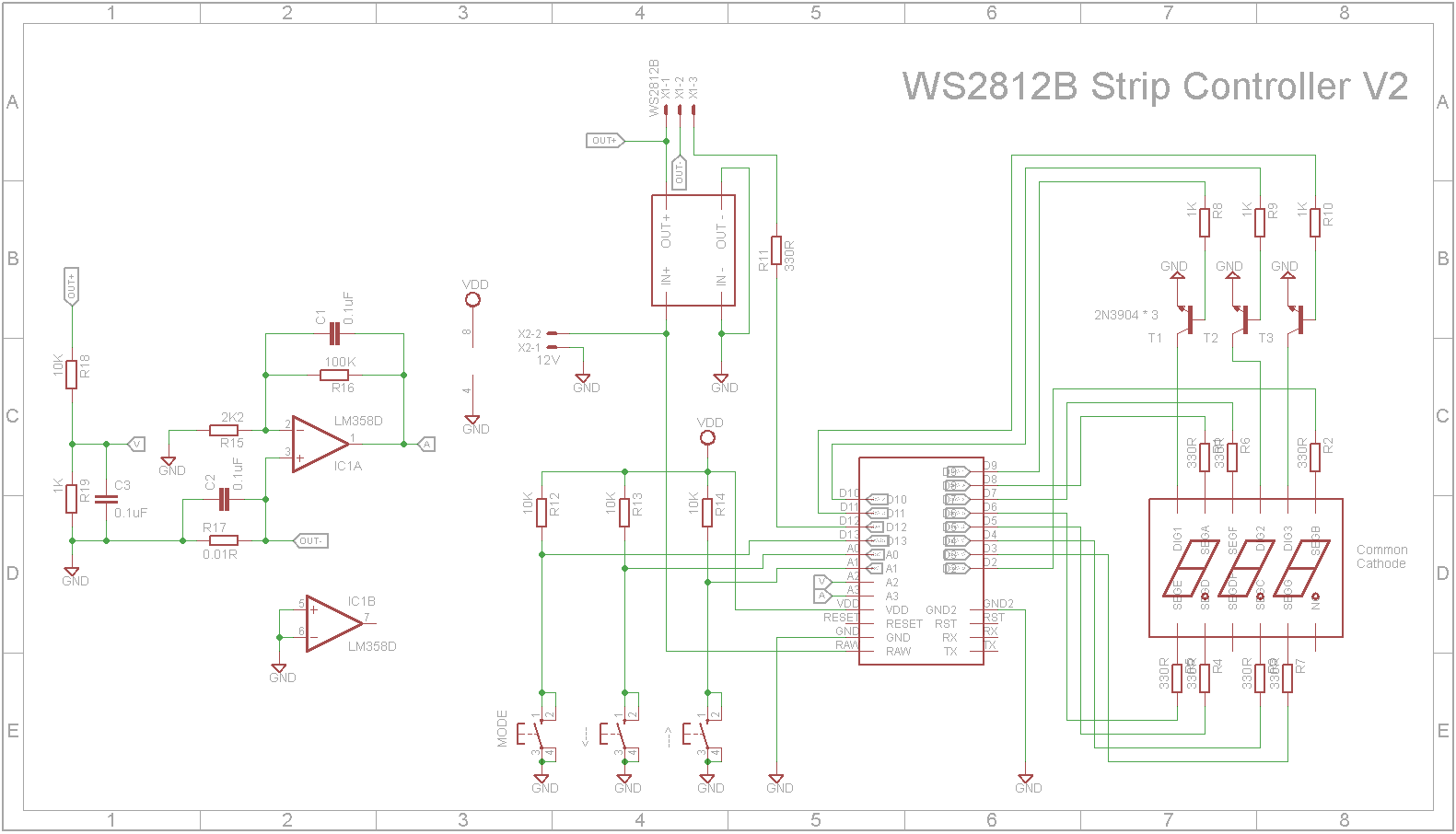


_3u05Tpwasz.png?auto=compress%2Cformat&w=40&h=40&fit=fillmax&bg=fff&dpr=2)
Comments