


Hardware components | ||||||
| × | 1 | ||||
| × | 1 | ||||
| × | 1 | ||||
| × | 1 | ||||
 |
| × | 2 | |||
| × | 1 | ||||
| × | 1 | ||||
 |
| × | 1 | |||
| × | 1 | ||||
| × | 1 | ||||
| × | 1 | ||||
 |
| × | 1 | |||
Software apps and online services | ||||||
 |
| |||||
Hand tools and fabrication machines | ||||||
 |
| |||||
 |
| |||||
Recently I built a function generator based around a AD9833 module. In that project I used the blue variant. This is the basic module and just holds the AD9833 and 25MHz crystal clock. At the same time I also bought the green variant but I couldn't find any schematics or code examples on how to use it. It also includes a MCP41010 digital potentiometer and AD8051 high speed, rail-to-rail amplifier.
I had some OPEN-SMART 1.8 Inch 128x64 SPI Monochrome LCD displays that I brought from Ali-Express some time ago. This seemed like the ideal project to figure out how to use both these devices.
One of the issues I had when using my first AD9833 Function Generator was when you changed the waveform, the amplitude would change. So in this version I wanted to control the digital potentiometer in such a way as to keep the peak-to-peak value of the output waveform constant no matter which waveform was being outputted.
To achieve this, there is a table of settings in the software for each 0.1V step of output for each waveform. I limited the output to a maximum of 1V.
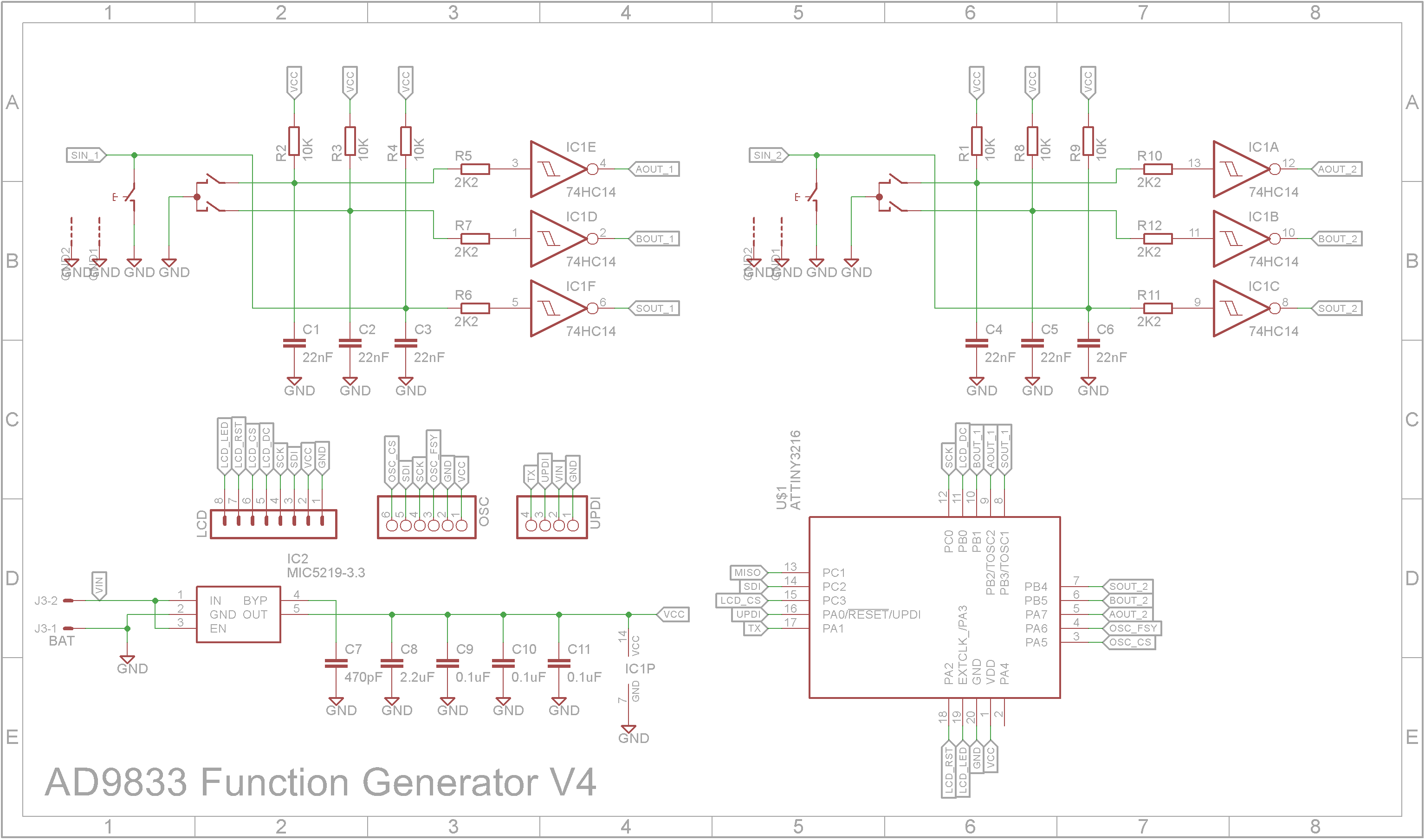
SchematicAs the LCD display can only accept voltages of 3.3V, I decided to power the final unit using a single 18650 3.7V to 4.2V lithium battery with a TP4056 charging module. Because the battery voltage can drop down to 3.7V when it discharges, I used a low drop-out voltage (LDO) regulator to supply the unit.
The microprocessor is a ATtiny3216. Two rotary encoders are used. One controls the frequency while the other controls the amplitude of the output. All contacts are hardware de-bounced using a RC network and Schmitt trigger.
3D printingAll 3D printing is done using a 0.2mm layer height. You will need to rotate the parts in your slicer software so they will sit flat on the build plate. No supports are required.
When printing "Box - Text V4.stl", switch to a contrasting color at the start of layer 4. Use double-sided tape or glue to join "Box - Text V4.stl" to "Box - Front Half V4.stl".
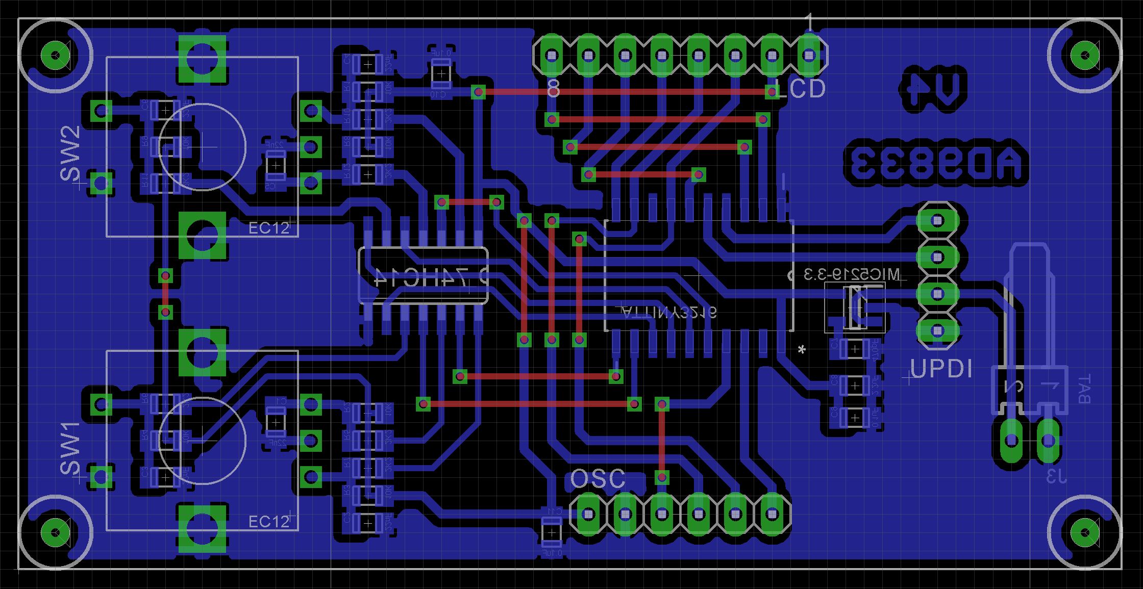
LayoutSMD components were used where possible. The two rotary encoders are soldered to the board which is in turn screwed onto the front panel. The LCD display also plugs into the board simplifying any external wiring. The only wire needed is the power wires and the 6 wire cable that goes to the AD9833 board.
The AD9833 board comes with a SMA female connector. You need to solder this onto the board. The board is then fixed to the front panel.
The Eagle files have been included should you wish to have the board commercially made or you can do as I did and make it yourself. I used the Toner method.
AssemblyStart by adding the SMD components. I find it easier to use solder paste rather than use solder from a reel when soldering SMD components. I used my SMD Hot Plate to reflow the solder paste.
Add the links if your board is single sided.
Add the 4 pin and 6 pin straight headers and the KF2510 2 pin male right angle connector to the copper side of the PCB.
Add the two rotary encoders.
Add a 8 pin 5mm straight female header to the PCB. (Note standard headers are usually 8.5mm).
3D print "LCD Support V4.stl" and glue the spacers to the PCB
Plug in the display.
Screw on the AD9833 module to the front panel using two M2.5 4mm screws.
Screw on the main PCB to the front panel using four M2 6mm screws.
Connect the two boards using a 10cm 6 way Dupont cable. I removed the single shrouds and replaced them with six pin shrouds.
Add the power switch. I connected the switch to a two pin male Dupont connector so that it I could unplug the front panel from the back panel.
Hammer in two M2.5 3.5 x 4 brass inserts into the back panel to hold the battery
Screw on the ABS battery holder using two 4mm M2.5 screws.
Solder the battery and output wires to the TP4056 Type C battery charger module and fit into its holder.
Instead of soldering the positive lead to the switch on the front panel, I glued on a two pin straight female Dupont socket so the wires to the switch can be unplugged.
Close the clam-shell case using four 6mm M3 screws.
The ATtiny3216 is part of the new breed of ATtiny microprocessors. Unlike the earlier series such as the ATtiny85, the new breed use the RESET pin to program the CPU. To program it you need a UPDI programmer. I made one using a Arduino Nano. You can find complete build instructions at Create Your Own UPDI Programmer. It also contains the instructions for adding the megaTinyCore boards to your IDE.
Once the board has been installed in the IDE, select it from the Tools menu.
Select board, chip (ATtiny3216), clock speed (20MHz), millis()/micros() timer (TCD0) and the COM port that the Arduino Nano is connected to.
The Programmer needs to be set to jtag2updi (megaTinyCore).
Open the sketch and upload it to the ATtiny3216.
Using the function generatorThe function generator is controlled by two rotary encoders. Each rotary encoder shaft is a push switch.
Frequency rotary encoder
The current mode is shown on the last line. Pushing the knob will switch between the following modes:
- x1Hz - Turning the rotary encoder will increase or decrease the frequency by 1Hz
- x10Hz - Turning the rotary encoder will increase or decrease the frequency by 10Hz
- x100Hz - Turning the rotary encoder will increase or decrease the frequency by 1-100Hz
- x1kHz - Turning the rotary encoder will increase or decrease the frequency by 1, 000Hz
- x10kHz - Turning the rotary encoder will increase or decrease the frequency by 10, 000Hz
- x100kHz - Turning the rotary encoder will increase or decrease the frequency by 100, 000Hz
- x1MHz - Turning the rotary encoder will increase or decrease the frequency by 1, 000, 000Hz
- Waveform - Turning the rotary encoder will switch the waveform between SINE, TRIANGLE and SQUARE
- Backlight - Turning the rotary encoder will increase or decrease the backlight by 1%
Amplitude rotary encoder
Pushing the knob will switch turn on/off the output.
Rotating the rotary encoder will increase or decrease the amplitude by 0.1V
ConclusionHaving a digital potentiometer and high frequency amplifier is a nice addition to the AD9833 board. Unfortunately the resolution of the amplitude was disappointing. Even using 0.1V steps, it is impossible to output the exact voltages. Also it doesn't address the issue of attenuation of the output signal when frequencies exceed around 500kHz. But considering the module costs around $5, it might be asking a bit too much to expect more from it.
All-in-all, it was an interesting build and the interfacing with the AD9833 module and display module was successful. As for a piece of test equipment for the workshop, for audio work it is more than adequate.


Comments