

Hardware components | ||||||
 |
| × | 1 | |||
| × | 1 | ||||
 |
| × | 1 | |||
 |
| × | 1 | |||
 |
| × | 1 | |||
| × | 1 | ||||
| × | 1 | ||||
| × | 1 | ||||
| × | 2 | ||||
 |
| × | 2 | |||
| × | 1 | ||||
| × | 1 | ||||
Software apps and online services | ||||||
 |
| |||||
Hand tools and fabrication machines | ||||||
 |
| |||||
 |
| |||||
The purpose of the project was to test the Analog Devices AD9833 Programmable Waveform Generator chip. On eBay, Ali-Express and other similar sites you can purchase a AD9833 module for around $5 including shipping.
FEATURES
- Digitally programmable frequency and phase
- 12.65 mW power consumption at 3 V
- 0 MHz to 12.5 MHz output frequency range
- 28-bit resolution: 0.1 Hz at 25 MHz reference clock
- Sinusoidal, triangular, and square wave outputs
- 2.3 V to 5.5 V power supply
- No external components required
- 3-wire SPI interface
- Extended temperature range: −40°C to +105°C
It is a very impressive module and with that endorsement, the original project was extended to become a useful tool for the work bench.
Demonstration3D Printing"Box - Back V2.stl" - 0.2mm layer height, 20% infill, Rotate 90 degrees about the Y axis, no supports
"Box - Bot V2.stl" - 0.2mm layer height, 20% infill, Rotate 180 degrees about the Y axis, no supports
"Box - Front V2.stl" - 0.2mm layer height, 20% infill, Rotate 90 degrees about the Y axis (text facing up), no supports, change to contrasting filament a start of layer 11.
"Box - Knobs V2.stl" - 0.1mm layer height, 50% infill, no supports, change to contrasting filament a start of layer 120.
"Box - Top V2.stl" - 0.2mm layer height, 20% infill, no supports.
Drill out the four PCB supports on "Box - Top V2.stl" with a 2.5mm drill and create a thread with a 3mm tap.
The lugs that hold the shells together are a bit fragile. I glued on washers before I drilled the holes with a 2.5mm drill and created a thread with a 3mm tap. Drill out the holes that the screws go through with a 3mm drill.
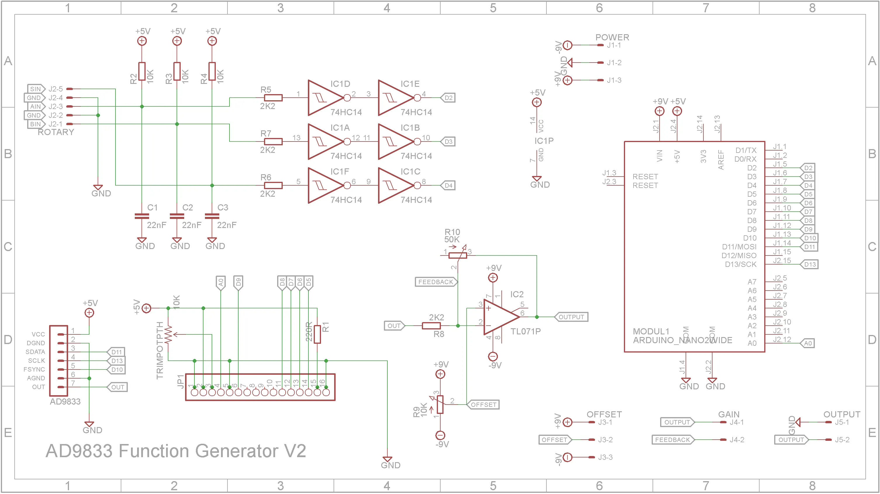
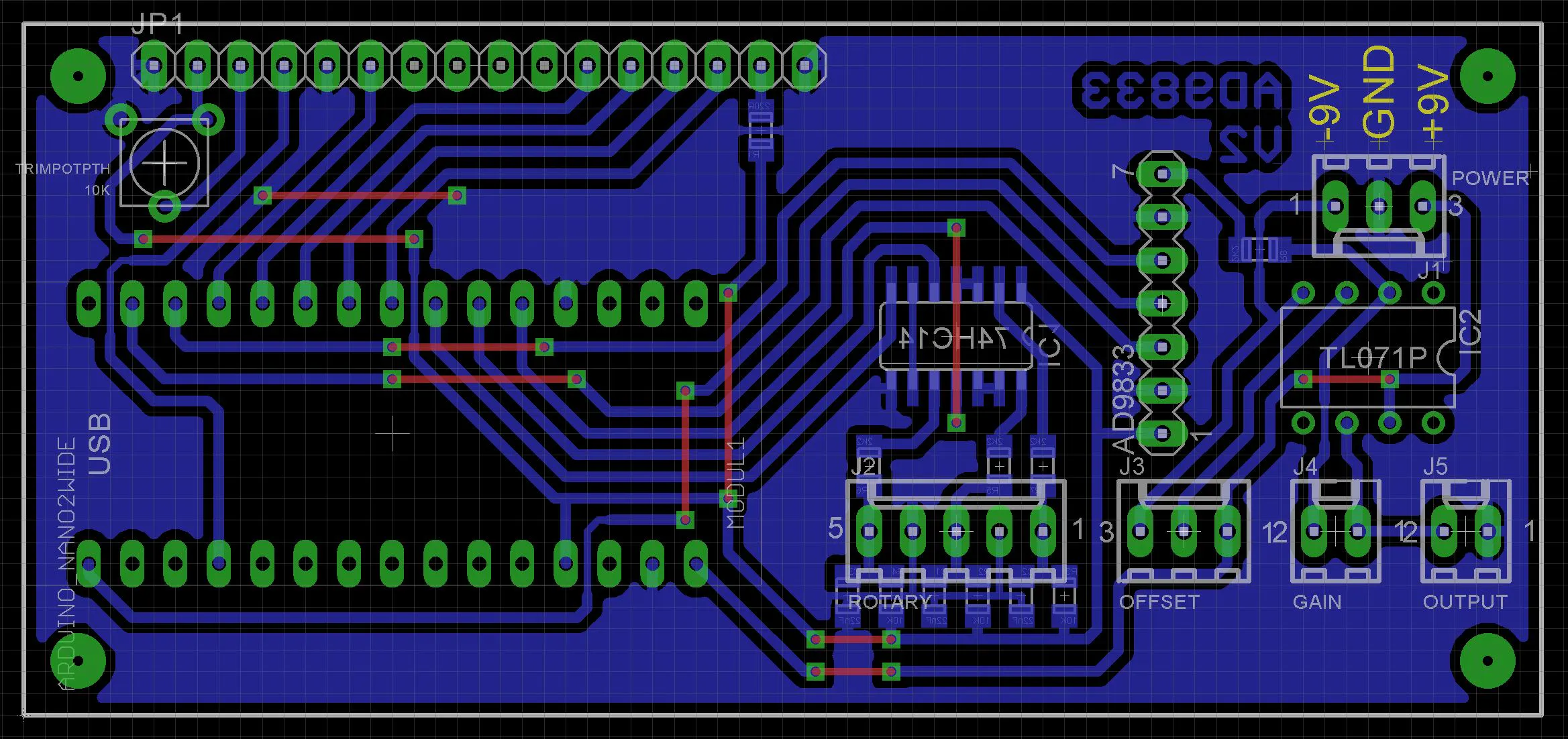
The Case & PCB is designed to fit to the top of the case and to eliminate the wiring to the LCD 1602 display. The Eagle files have been included should you wish to have the board commercially made or you can do as I did and make it yourself. I used the Toner method.
Start by adding the SMD components. I find it easier to use solder paste rather than use solder from a reel when soldering SMD components.
I used my PCB Reflow Hot Plate to reflow the solder paste
Add the links if your board is single-sided.
Add the 10K trim-port that adjust the LCD contrast.
Add the TL071 op-amp to the board. The 8-pin IC socket is optional.
Add the Arduino Nano to the board.
Add the headers for the Rotary Encoder, Level Potentiometer, BNC output socket and power supply. Only the power supply connector really needs to be polarized.
Add the 7 pin low right-angle male header on the AD9833 module and solder to the component side of the board.
NOTE:
To keep the unit as small as possible, the OFFSET potentiometer was removed and the corresponding connector on the PCB was replaced with a trim-pot. It is set so the waveform has equal amplitude either side of ground.
The LCD 1602 display is connected to the PCB via a 16-pin right-angle high male pin header.
Solder the pin header to the LCD 1602 display board as shown below
Sit the PCB on the pins but don't solder them in yet.
Screw the PCB onto "Box - Top V2.stl" using four 6mm M3 screws.
Add the front panel so that the LCD 1602 display sits in the hole provided. Make sure the front panel is seated correctly and mark where you need to solder the pins on the PCB.
Unscrew the PCB and solder the display board to the main PCB.
Finally add the rotary encoder, level potentiometer and BNC connector to the front panel. Solder on the connection wires that go to the PCB.
Screw on two 9V battery holders to the pillars provided. You can either use small self taping screws or drill out the holes with a 1.8mm drill and use six 4mm M2 screws.
The power switch is a standard 21mm x 15mm DPDT or DPST rocker switch. The switch needs to switch both the negative and positive sides of the -9V, 0V, +9V dual battery assembly.
Close the clam-shell case using four 6mm M3 screws.
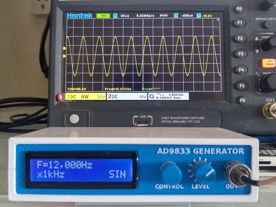
Software / ProgrammingConnect the USB cable to the Arduino Nano and upload the software via the Arduino IDE.
The software has be rewritten from the original code used in GreatScottLab's version. The changes made are:
- Single channel only
- Removed phase settings
- Removed on/off setting
- Removed software de-bouncing (now done in hardware)
- Simplified menu system - Pushing the rotary encoder knob switches between x1Hz, x10Hz, x100Hz, x1kHz, x10kHz, x100kHz, x1MHz and Waveform. Rotating the rotary encoder knob will either change the frequency using the selected step rate or change the waveform being outputted.
- Menu changes are applied automatically to the output.
- Any changes made to the settings are written back to EEPROM every minute so that the AD9833 Generator will start up from its last recorded setting.
Overall the final appearance looks nice on the benchtop. The output from the generator is good up to around 150kHz. After that attenuation of the output starts to occur. This is probably due to the TL071 op-amp rather than the AD9833 module itself.
All-in-all, it was a fun build, it looks professional. For audio work it is more than adequate.


_3u05Tpwasz.png?auto=compress%2Cformat&w=40&h=40&fit=fillmax&bg=fff&dpr=2)
Comments