
Hardware components | ||||||
| × | 1 | ||||
| × | 1 | ||||
 |
| × | 1 | |||
| × | 1 | ||||
| × | 1 | ||||
| × | 1 | ||||
 |
| × | 9 | |||
 |
| × | 2 | |||
 |
| × | 1 | |||
| × | 1 | ||||
Software apps and online services | ||||||
 |
| |||||
Hand tools and fabrication machines | ||||||
 |
| |||||
 |
| |||||
Sometimes during a build, you may need to drill holes of a fixed depth. I have a Dremel Drill Press and while it is a useful tool, the "depth gauge" that is incorporated is sometimes problematic.
The problem is that over time either due to vibrations or hitting the stop, it will move making the subsequent holes deeper than the first hole drilled.
After reading Thomas Angielsky's Drill Depth Display with Gyro Sensor build, I wondered how I might make something like it for my Dremel Drill Press. Fixing a gyro sensor to the handle didn't seem practical. Also having to fix anything to the Drill Press or having wires floating around didn't seem a good idea either.
The solution I ended up using was a magnet and a linear hall sensor.
Video3D PrintingTo simplify printing, the display module and cover for the Dremel Drill Press are printed separately. You can take the STL files to a 3D print shop if don't have access to a 3D printer.
Drill Depth Mount.stl - 0.2mm Layer height, supports touching build plate only
Drill Depth Spacer.stl - 0.2mm Layer height, no supports
Drill Depth Display.stl - 0.2mm Layer height, all supports
Drill Depth Back.stl - 0.2mm Layer height, no supports
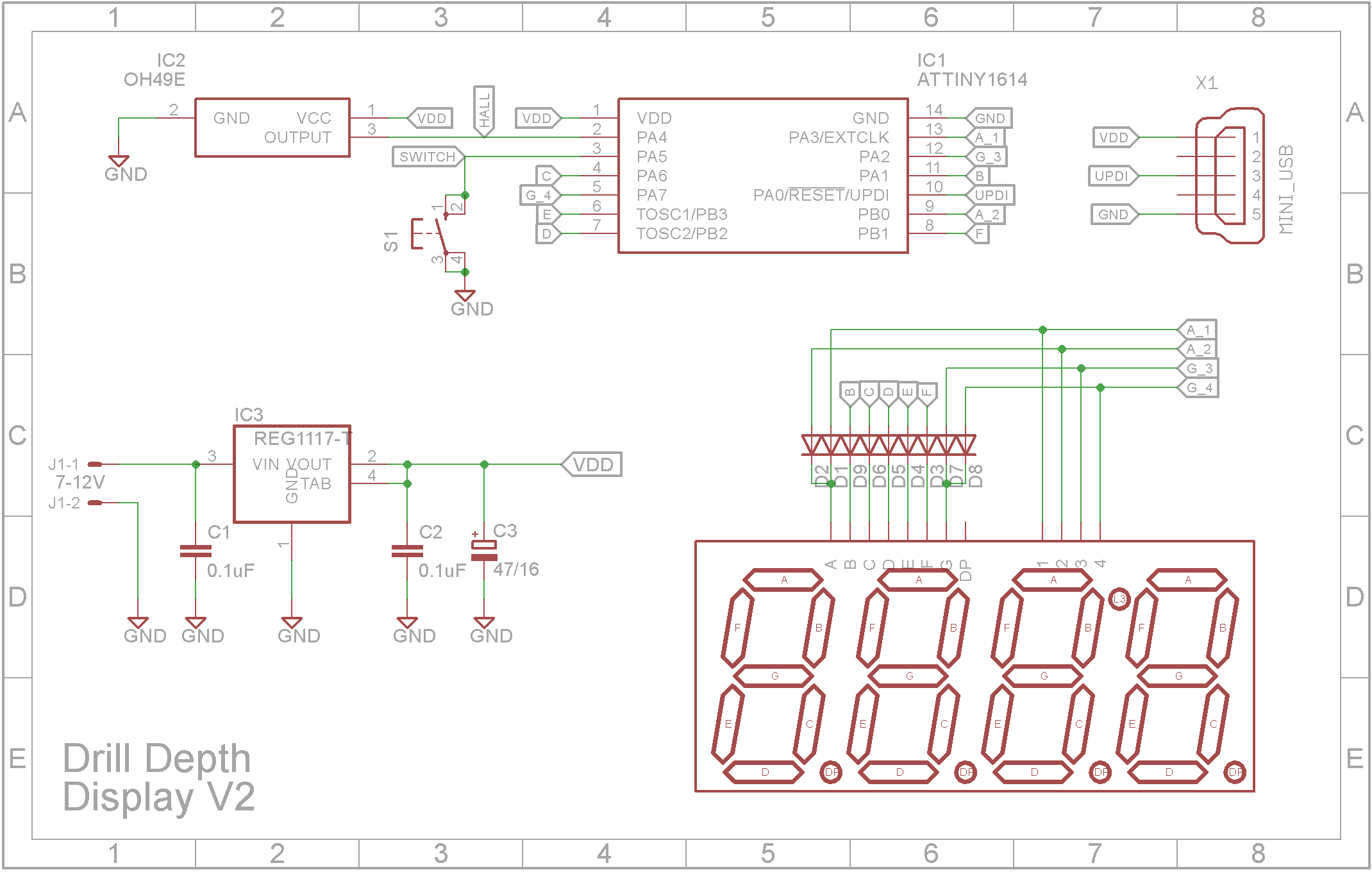
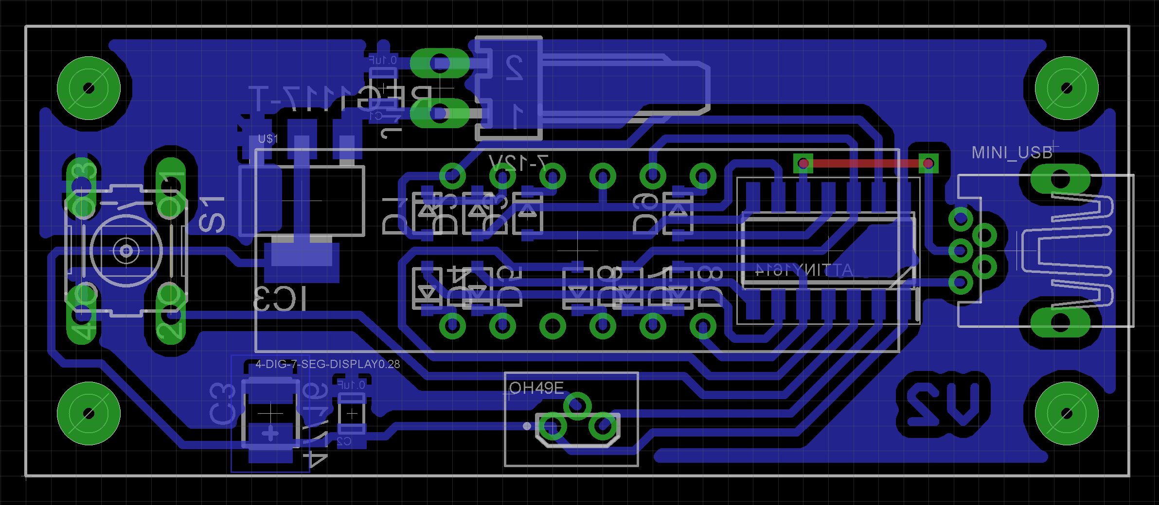
BuildYou will need a printed circuit board (PCB). The Eagle files are attached should you wish to have the PCB commercially made or do as I did and make it yourself. I used the Toner method.
Start by adding the SMD components. I find it easier to use solder paste rather than use solder from a reel when soldering SMD components.
If your board is single sided, there is one link to add on the top side.
When putting in the top side components, place the 3D printed "Drill Depth Spacer.stl" under the display so it sits as high as possible off the board. Also super glue the button top on the switch shaft. Make sure the glue doesn't run down the shaft and into the switch.
Screw the board into the case using 4 x 6mm M3 screws. The OA49E sensor should appear centered in the hole.
The unit can either be powered via the USB Mini socket or a 9V battery. If you decide to include the battery, a switch hole is provided for a miniature slide switch. I got this from eBay years ago and don't remember the exact details. It is a SPDT slide switch with a 6x3 slide area and the mount holes are 15mm centers. Fit the slide switch over the plastic lugs and melt the lugs with a soldering iron to hold the switch in place.
The ATtiny1614 is part of the new breed of ATtiny microprocessors. Unlike the earlier series such as the ATtiny85, the new breed use the RESET pin to program the CPU. To program it you need a UPDI programmer. I made one using a Arduino Nano. You can find complete build instructions at Create Your Own UPDI Programmer. It also contains the instructions for adding the megaTinyCore boards to your IDE.
The USB socket provides power to the unit. The UPDI pin of the ATtiny1614 processor is connected the D+ pin on the USB socket. This allows the programming of the ATtiny1614 using a custom cable. USB Mini plugs are available on eBay or you can cutup an old USB Mini cable.
Once the board has been installed in the IDE, select it from the Tools menu.
Select Board, chip, clock speed and the COM port that the Arduino Nano is connected to.
The Programmer needs to be set to jtag2updi (megaTinyCore).
Open the sketch and upload it to the ATtiny1614.
Using the unitOn power on, the display will show the relative magnet field intensity. (If above 512, your magnet is upside-down. It should read around 120). Pressing the button for more the 300mS will set the zero point. As you move the drill down, the display shows an increasing number as the magnet field intensity decreases. It doesn't appear to be linear but it is consistent. The number shown is arbitrary, that is it doesn't represent any known unit of measurement. As long as every position shows a consistent value, the number can be used to set a specific depth.
Once you have the depth you want to record, give the button a short press and the software will store the value. The display will count down from the top to the chosen position. Once the position is reached, the display will show the word "Stop".
ConclusionThe unit works quite well. It would be nice if the display showed milli-metres but it's not a show stopper. It did forget about the cord on the actual Dremel Drill itself. It comes out the top of the drill and can therefore cover the display. Fortunately the display unit can be rotated so the cord doesn't cover the display.
A special thanks to Thomas Angielsky for the inspiration.


Comments